
Related Manuals for Dynisco ATC770-0-2-3


Summary of Contents for Dynisco ATC770-0-2-3
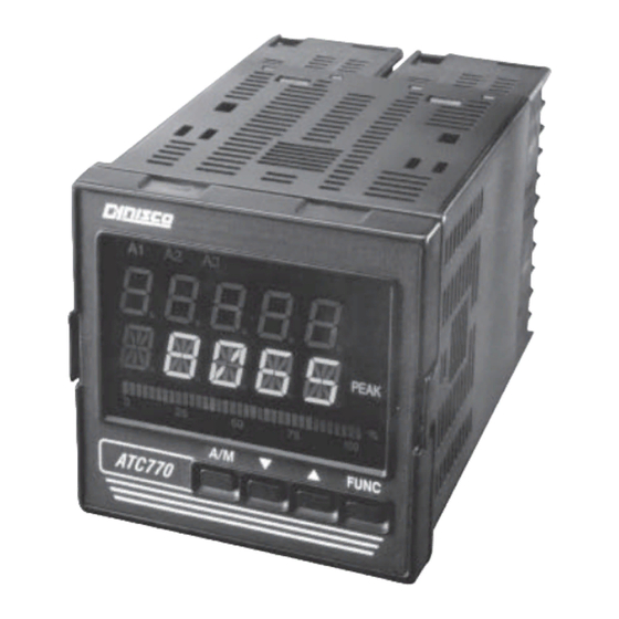
- Page 1 ATC770 Microprocessor-Based Pressure/Process Controller Installation and Operation Manual P/N 974086 12/04 Rev. G ECO # 29250...
-
Page 2: Table Of Contents
ONTENTS Quick Start Instructions ........................3 1. Introduction ..........................8 2. Specifications ........................... 8 3. Unpacking ..........................17 4. Mounting and Wiring ......................18 5. Start Up Procedures ........................ 24 6. Configuration ......................... 31 7. Operation ..........................45 8. Instrument Calibration ......................53 9. -
Page 3: Quick Start Instructions
ATC770 Microprocessor-Based Pressure/Process Controller ATC770-0-2-3 Q ODEL UICK TART NSTRUCTIONS OUNTING • Prepare panel cutout to dimensions shown below. • Remove instrument from case by spreading locking tabs. • Grasp the bezel and slide the instrument out of its case. - Page 4 IRING • Connect the wires from transducer cable as shown in the terminal diagram. • Connect final control device. • Connect alarm(s) if applicable. Note that alarm defaults are High, Reverse Acting for alarms 2 & 3 - alarm 1 is low inhibited. •...
- Page 5 ATC770 Microprocessor-Based Pressure/Process Controller • Return to GROUP none and observe that the value in the upper display is the actual setpoint you wish to control. • When the SMART LED has stopped flashing, press and hold the A/M key for at least 5 seconds. The manual LED will extinguish, and you will be automatic control mode.
- Page 6 NDEX How to: See Section: Page Wire the ATC770 4.1, 4.2 22, 23 Primary Input Set the Primary Input Type 6.1.1, 6.1.3 31, 34 Set the Shunt Calibration 6.1.2 Set the Primary Input Full Scale Value 6.1.4 Set the Primary Input Failsafe Mode 6.1.7 Calibration of Primary Input Calibrate the Primary Input to the instrument...
-
Page 7: Instrument Maintenance And Repair
ATC770 Microprocessor-Based Pressure/Process Controller Instrument Maintenance and Repair Instrument Maintenance Repair the Instrument Get Technical Assistance... -
Page 8: Introduction
NTRODUCTION The ATC770 Pressure/Process Controller is a microprocessor-based instrument, with the capability of controlling an extruder or other process using an advanced proprietary SMART self-tuning algorithm. The input is user configurable to be 350 Strain Gage, high-level voltage or high level current. - Page 9 ATC770 Microprocessor-Based Pressure/Process Controller Rear Terminal Block: 34 screw terminals with rear safety cover & E OWER UPPLY NVIRONMENTAL PECIFICATION Main Power Supply: From 100 to 240 VAC (-15% to 10%), 50/60 Hz switching. Option: 24 V AC/DC (-10% to 10%) Power Consumption: Max 22 VA at 50 Hz;...
- Page 10 segment blinks for pressure greater than full scale value. Indicators: 9 red LED’s annunciator for: Lit when alarm 1 is in Alarm State Lit when alarm 2 is in Alarm State Lit when alarm 3 is in Alarm State SMRT Flashing when the first step of SMART algorithm is activated Lit when the second step of SMART algorithm is activated Lit when device is in manual mode...
- Page 11 ATC770 Microprocessor-Based Pressure/Process Controller Sampling time: 50 ms typical. Display Update Time: 400 ms. Engineering Units: Peel-off labels. Calibration Mode: Field calibrations (zero and span) are applicable for both strain gage and linear input. Moreover it is possible to delete the field calibration done by the end user and to restore original factory calibration values.
- Page 12 2.5 P & R RESSURE EMOTE OINT NPUTS OMMON PECIFICATION Common Mode Rejection Ratio: 120 dB @50/60 Hz Normal Mode Rejection Ratio: 60 dB @ 50/60 Hz Reference Accuracy: ± 0.2% of full scale value ± 1 digit @ 25 ± 10°C and nominal power voltage. Operative accuracy - temperature drift: <300 ppm/°C of full span for current, voltage and strain gage input IGITAL...
- Page 13 ATC770 Microprocessor-Based Pressure/Process Controller Alarm Outputs: 3 standard alarms (AL1, AL2 and AL3). AL1 and AL2 Contacts: 1 SPDT 2 A max @ 240 VAC resistive load. AL3 Contacts: 1 SPST solder jumper selectable NO/NC 2 A max @ 240 VAC resistive load. Contact Protection: Varistor for spike protection.
- Page 14 Format: 1 start bit, 8 bits with or without parity, 1 stop bit Parity: Even/Odd. ONTROL UTPUT PECIFICATION Control Output: Opto-isolated from CPU input and output circuits. Type of Analog Output: Jumper and keyboard selectable between: • + 0/10 VDC min. load 5 K •...
- Page 15 ATC770 Microprocessor-Based Pressure/Process Controller 2.11 ONTROL AND ETRANSMISSION UTPUTS OMMON PECIFICATION Reference Accuracy: ±0.1% of output span @ 25 ± 10°C and nominal line voltage. Linearity Error: <0.1% of output span. Output Noise: <0.1% of output span. 2.12 ONTROL LGORITHM PECIFICATION Control Type: PID plus Integral Preload plus Anti-Reset Windup Output Value Indication: Selectable between the following Modes:...
- Page 16 response. It is capable of estimating the process parameters with high precision. 2. ADAPTIVE ALGORITHM In order to implement the adaptive algorithm, the instrument should be in automatic mode. Then change SMART to ON. In this case the ON will be remembered by the instrument even if the instrument was switched off.
-
Page 17: Unpacking
ATC770 Microprocessor-Based Pressure/Process Controller CnCt . It will increase the set point in a linear fashion (about 20 seconds from 0 to 100% output). Digital Input 3 (DIG3) is available only when the Group 1 function A/M is changed from LoCAL to CnCt . -
Page 18: Mounting And Wiring
ATC770 B LOCK IAGRAM Fig. 1 ATC770 Electronics Layout Block Diagram NOTE: Dashed Line represents insulation boundary. OUNTING AND IRING Please refer to Figure 2 for cutout dimensions and clearance requirements. Locate the two mounting brackets packed with the instrument and have them available. 1. - Page 19 ATC770 Microprocessor-Based Pressure/Process Controller Fig. 2 ATC770 Outline Drawing...
- Page 20 2. Slide the instrument case into the cutout, being sure that it is right-side-up (terminal 1 at the top). Attach the panel mounting hardware at diagonally opposite sides of the top and bottom of the case, tightening the threaded rod until the case is secure against the panel. 3.
- Page 21 The power supply input is fuse protected by a sub miniature fuse rated T, 1A, 250V. When the fuse is damaged, it is advisable to verify the power supply circuit. It may be necessary to send back the instrument to Dynisco for service. The safety requirements for Permanently Connected Equipment say: •...
- Page 22 ERMINAL SSIGNMENTS Linear - Remote Setpoint Input Linear + Strain Gage Signal + or Linear + Strain Gage Signal - or Linear - Calibration 2 Primary Input Excitation + Excitation -, Calibration 1 Main Output mA/V + Main Output mA/V - Remote Reset Remote Reset Alarm 1.
-
Page 24: Start Up Procedures
TART ROCEDURE ONFIGURATION The ATC770 is shipped with the hardware jumpers set for the following: 1. Main Input (Pressure) - Strain Gage 2. Main Output - Voltage 3. Secondary Output - Voltage In addition, the DIP switches controlling the software security lock codes are in the “OFF” positions. Please ensure that the correct jumper settings for the input(s) and output(s) used in your particular application are selected. - Page 25 ATC770 Microprocessor-Based Pressure/Process Controller Successively pressing FUNC will scroll through all the parameters of GROUP 1. The last two parameters of each group allow the default parameters to be restored, and returns to GROUP . If nonE is chosen in the group access function, the instrument will return to normal operating mode after pressing of the FUNC key.
- Page 26 5.2.3 PERATING ESCRIPTION The FUNC key is used to access the parameters organized in five groups. Use the FUNC pushbutton to access the Group 1 parameters; the last entry (showing Group and nonE ) is intended to access the other groups of parameters, or pressing FUNC again returns to the normal display mode.
- Page 27 ATC770 Microprocessor-Based Pressure/Process Controller values must be set and the shunt capability enabled. The Shunt Calibration value is a percentage of the full scale transducer range. If the Shunt Value is supplied as a pressure, it must be converted to percent.
- Page 28 NOTE: A dry contact switch or relay must be fitted between terminal 62 (Common) and terminal 63 (Digital Input 1 Remote AUTO/MAN (DIG1)) to enable the use of Digital Input 2 (DIG2) and 3 (DIG3) (Control output value increase and decrease). To verify this parameter or to change it, press the FUNC key until the lower display shows A/M .
- Page 29 ATC770 Microprocessor-Based Pressure/Process Controller 5.4.1 S ETTING THE EMOTE OINT NPUT OLTAGE OR URRENT To change or view the Remote Set Point selection parameter, press the FUNC key until nonE and GROUP show on the display. Press the key until 5 shows in the upper display. Press the FUNC key until the lower display changes to RI.TYP .
- Page 30 Fig. 6 Remote Set Point Jumper Location, Board E...
-
Page 31: Configuration
If you have an amplified transducer, or other amplified input, skip to Section 6.1.2, otherwise, if using a Dynisco transducer, the model number of the transducer will designate its own electrical output. For example, in plastic melt applications, the PT462E-5M-6/18 or TPT432A-10M-6/18 have... - Page 32 a strain gage (0-3.33 mV/V full scale) signal output. Amplified units have a number where the strain gage units have a letter (E or A). The PT4624-5M-6/18 has a 4-20 mA signal output; the PT4625-5M- 6/18 has a 0-5 VDC signal output, while PT4626-5M-6/18 has a 0-10 VDC signal output. In Industrial applications, amplified units have a middle or end number of 4, 5, or 6.
- Page 33 MPLIFIED RANSMITTERS The Dynisco strain gage transducers and amplified transmitters (if so equipped) have an internal shunt to allow the ATC770 to set the internal scaling for correct display. To Access the Shunt Calibration parameter, press the FUNC key until nonE and GROUP show on the display. Press the key until 4 shows in the upper display.
- Page 34 Dynisco transducers have an 80% shunt value so no changes need be made. However, some transducers and strain gages have shunt values that may range from 40% to 100%. If so, press the key until the upper display changes to the correct values. Press the FUNC key to set the value.
- Page 35 ATC770 Microprocessor-Based Pressure/Process Controller Fig. 9 Input Selection J84 for Amplified Input 6.1.4 S ETTING THE RIMARY NPUT CALE ALUE The model number of the transducer or transmitter will designate the full-scale pressure capability. For example, model number TPT432A-5M-6/18 indicates that the full-scale pressure is 5,000 (5M), while the PT150-5C indicates that the full-scale pressure is 500 (5C).
- Page 36 6.1.5 S ETTING THE RIMARY NPUT CALE ALUE For applications where a low scale value is non-zero, the Instrument can provide a low scale value of ±25% of the full scale value. To set the low-scale value, press the FUNC key until nonE and GROUP show on the display. Press key until 3 shows in the upper display.
- Page 37 ATC770 Microprocessor-Based Pressure/Process Controller Normally Closed Contact are held OPEN, while the Normally Open contacts are held CLOSED. On power failure, they are released. On start-up, a Low Alarm may cause the unit to go into an undesired alarm condition prior to reaching running conditions.
- Page 38 6.2.3 S ETTING THE ILTERING FOR LARMS Filtering is an electrical method of averaging the input values over a period of time to arrive at a smoother curve. This helps to eliminate short duration transients and spikes which can cause alarms, but which may cause false or spurious readings.
- Page 39 ATC770 Microprocessor-Based Pressure/Process Controller options for failsafe mode are either FS for failsafe mode, or nFS for non-failsafe mode. Press the keys until the upper display changes to the desired value. Press the FUNC key to lock in the value and advance to the next parameter. Similarly, you may configure Alarm 2 (A2.FSM) and Alarm 3 (A3.FSM) .
- Page 40 upper display shows the selected type. Press the keys until the upper display changes to the desired value. Then press the FUNC key to lock in the value. Press A/M to return to the operating screen. Next, select the jumper setting necessary. See Figure 10 below: Fig.
- Page 41 ATC770 Microprocessor-Based Pressure/Process Controller 6.3.2 S ETTING THE ETRANSMISSION UTPUT ANGE To change or view the Retransmission Output Range Low, press the FUNC key until nonE and GROUP show on the display. Press the key until 3 shows in the upper display. Press the FUNC key until the lower display changes to RO.LO .
- Page 42 using jumpers. To select the voltage or amperage range, press the FUNC key until nonE and GROUP show on the display. Press the key until 5 shows in the upper display. Press the FUNC key until the lower display shows CO.TYP . Using the keys, select the desired value: 0-5 (VDC), 0-20 (mA), 4-20 (mA), 0-10 (VDC), or -10.10 (VDC).
- Page 43 ATC770 Microprocessor-Based Pressure/Process Controller 6.4.2 M AKING THE ONTROL UTPUT IRECT EVERSE ELECTION The input signal can cause the control output to either increase or decrease with an increasing or decreasing input signal. The table below shows the value of Direct/Reverse Control Output selection (CO.D/R) .
- Page 44 desired value from -10000 to the CO.HI value. (if no CO.HI value has been set, you may need to return to this step. When finished, press the FUNC key to lock in the value. The lower display will show CO.HI , and the upper display will show the default value (100.0). Using the keys, select the desired value from 0 to 10000 for the CO.HI value.
-
Page 45: Operation
ATC770 Microprocessor-Based Pressure/Process Controller 6.5.1 S ETTING THE ECURITY ODE FOR EVEL To view or change the security code, press the FUNC key and the lower display changes to CODE.A . The upper display shows 0 , which indicates no security, and 1 means all parameters related to levels A, B, and C are always locked). - Page 46 Be sure that the full scale and low scale values ( PI.FSV and PI.LSV ) have been set to match the range of the transducer and that the SHUNT function is ON and set to the correct percentage (80% for a typical Dynisco transducer). To calibrate the transducer to the instrument, press the FUNC key until nonE and GROUP show on the display.
- Page 47 ATC770 Microprocessor-Based Pressure/Process Controller key until 2 shows in the upper display. Press the FUNC key and the lower the display. Press the display changes to ZERO.C . The upper display shows OFF . Press the keys until the upper display changes to ON .
- Page 48 CLEAr . Press the FUNC key to restore the linear factory calibration of the span value. When the legend DSP.FL appears in the lower display, calibration is complete. Press A/M to return to the operating screen. SMART TART P AND NGAGING After Calibration of the Transducer to the Instrument, return to the main display.
- Page 49 ATC770 Microprocessor-Based Pressure/Process Controller 7.3.1 S ELECTING THE YPE OF ONTROL There are two types of control mechanisms that the ATC770 can use, either PID (Proportional, Integral, and Derivative), or PI (Proportional and Integral). The default value is PI , since a majority of the applications are extrusion motor control.
- Page 50 The Integral Time parameter (TI) follows the PB parameter. Its range is 1 to 10.000% and • changes to this parameter are inhibited during Adaptive Tune. • The Derivative Time parameter (DT) follows the TI parameter. Its range is 0.0 to 99.9 seconds and changes to this parameter are inhibited during Adaptive Tune.
- Page 51 ATC770 Microprocessor-Based Pressure/Process Controller display shows SMART . Press the key until the upper display changes to ON . Press the FUNC key to set the value. This will activate the Adaptive Tuner Algorithm, and will maintain the correct PID or PI parameters for the process. It will remain on until manually turned off. It will also come on anytime that the ATC770 is in Automatic mode.
- Page 52 7.3.6 A UTOMATIC OR ANUAL TART The ATC770 will allow for manual start-up and ramp to set point prior to controlling the process, or it can go directly to Automatic Start-Up where is controls the set point based on the previous data. This is generally a bad idea in motor control processes, and is discouraged.
-
Page 53: Instrument Calibration
The instrument is shipped fully calibrated and need not be further calibrated. Calibration of the ATC770 is a complicated procedure, requiring specialized equipment. Consult the Dynisco technical assistance line at 800-221-2201 before attempting to work on this instrument. The instrument calibrations are accessible by an internal dip-switch (see below). This is done to protect the calibration data area of the EEPROM. - Page 54 Fig. 13 ATC770 Board Location CPU BOARD DIP SWITCH POSITIONS Operating Mode SW1 OFF SW2 OFF Calibration Mode SW1 ON SW2 OFF Factory Mode SW1 OFF SW2 ON Security Mode SW1 ON SW2 ON ENERAL ALIBRATION ROCEDURE 1. Set the DIP switches to calibration mode as shown above. The upper display should show CAL while the lower display shows ATC .
- Page 55 UNDER ANY CIRCUMSTANCES 7. If the values CANNOT be made to correspond with the values in the Calibration Parameters Summary Table, the instrument must be sent to Dynisco for repair or re-calibration. RS-485 (O PTIONAL The ATC770 is available with an RS485 Digital communications port. The configuration parameters...
- Page 56 when equipped with this option, is compatible with Modbus and J-Bus protocols, the choice of which is made in the Configuration/Setup menu. 8.3.1 S ERIAL OMMUNICATION NTERFACE DDRESS This function is used to set the serial Communication Interface Address. To view or access this function, press the FUNC key until nonE and GROUP show on the display.
-
Page 57: Error Codes
FUNC key until nonE and GROUP Further documentation is available in Dynisco’s publication #974089 Modbus/J-Bus Protocol for Dynisco UPR700/ATC770 . Please contact Dynisco at 800-221-2201 for a copy of this manual. RROR On power up, the ATC770 will enter a self-test mode to evaluate the condition of the equipment. If an error is detected, the screen will show an error code number in the upper display and the mnemonic Err , in the lower display. - Page 58 / under the output limits. Correction: Check that the step change is correct; if it appears to be so, lower the change to a minimal value and try again. If the error still remains, send the instrument to Dynisco for repair (See Section 11.) Wrong zero measure.
- Page 59 (see Section 8.0), and re-power the instrument. In calibration mode, the registers will be properly re-written on power-up. When this is done return to normal operating mode. Failure of RAM circuit. There is no correction; the device needs to be sent to Dynisco for repair (See Section 11).
-
Page 60: Normative References
• Isopropyl Alcohol (pure or denatured) [(CH3)2CHOH) or • Water (H2O) • Always use the mildest means available 5. Verify that there are no loose terminals 6. Before re-inserting the instrument in its case, be sure that it is perfectly dry 7. -
Page 61: Parameter Group Menus
ATC770 Microprocessor-Based Pressure/Process Controller Part 4: Testing and measurement techniques - Section 8: Power frequency magnetic field immunity test IEC 1000-4-4: Electromagnetic compatibility (EMC) - Part 4: Testing and measurement techniques - Section 4: Electrical fast transient/burst immunity test ENV50141: Electromagnetic compatibility - Basic immunity standard - Conducted disturbances induced by radio-frequency fields - Immunity test ATC770 P... - Page 62 Group 3 Function Sec. As Set PI.FSV Primary Input Full Scale Value 6.1.4 PI.LSV Primary Input Low Scale Value 6.1.5 PI.DP Primary Input Decimal Point Position 6.1.6 A1.LNK Alarm 1 Input Channel Link 6.2.1 A1.TYP Alarm 1 Type 6.2.2 A2.LNK Alarm 2 Input Channel Link 6.2.1 A2.TYP...
- Page 63 ATC770 Microprocessor-Based Pressure/Process Controller Group 4 Function Sec. As Set LINE.F Line Frequency 5.3.6 DEFLT Loading Default Data 5.2.3 Group 5 Function Sec. As Set PI.TYP Primary Input Selection 6.1.1 RI.TYP Remote Set Point Input Selection 5.4.1 CO.TYP Control Output Selection 6.4.1 RO.TYP Retransmission Output Selection...
- Page 64 unlock operation also unlocks the parameters of the lower groups, while the lock operation locks all the parameters. To choose new security codes requires positioning of the internal dip-switches. In order to re-lock the different groups insert any number with the exception of the selected codes. AUTO/MANUAL SELECTION - Group 1 Available: Only if the external keyboard circuit is fitted.
- Page 65 ATC770 Microprocessor-Based Pressure/Process Controller LOADING DEFAULT DATA - Group 1 Available: Only if access to level A is allowed. Upper display: OFF Lower display: DEFLT Range: keys to switch the upper display from OFF to On 1, then press FUNC key to load the default data of the parameters belonging to group1.
- Page 66 Default value: OFF. TIME OF SMART FUNCTION - Group 2 Available: Only when SMART (TUNE) function is active. Upper display: During the automatic computation of the filter time constant the upper display shows the time constant selected by the algorithm. During the process analysis the upper display shows the elapsed time from the step change;...
- Page 67 ATC770 Microprocessor-Based Pressure/Process Controller algorithm is active. Lower display: TD Range: From 0.0 to 99.9 s. Default value: 0.0. AUTOMATIC SELECTION OF THE INTEGRAL PRE-LOAD VALUE - Group 2 Available: Always. Upper display: Setting this parameter to Auto causes the controller to calculate the integral pre- load value using the set point and process gain values.
- Page 68 Default value: nan. FILTER FOR DISPLAY AND CONTROLLER - Group 2 Available: Always. Upper display: Time constant for the sixth order filter acting on the display and on the controller. This filter is intended to remove the noise from input signal. Lower display: AT.FL Range: OFF, 0.5, 1, 2, 4, 8, 16 sec.
- Page 69 ATC770 Microprocessor-Based Pressure/Process Controller ALARM 1 FILTER - Group 2 Available: Only if A1.LNK is different than OFF. Upper display: Time constant of the alarm 1 filter. Lower display: A1.FL Range: OFF, 0.4, 1, 2, 3, 4, 5 sec. Default value: 0.4 sec.
- Page 70 Upper display: Full scale value. Lower display: PI.FSV Range: from 10 to 99950. Changes to this value affect the values for the pressure input low scale, the alarm set point limits, the set point limits, the set point and the retransmission limits.
- Page 71 ATC770 Microprocessor-Based Pressure/Process Controller Default value: Process alarm. ALARM 1 TYPE - Group 3 Available: Only if A1.LNK is different than OFF. Upper display: Selection of alarm 1 type. Lower display: A1.TYP Range: HI, LO, InhIb. High, low, low with mask at start-up. For band alarm high means outside band alarm, while low means inside band alarm.
- Page 72 CONTROL OUTPUT RANGE LOW - Group 3 Available: Always. Upper display: Range low for control output (for RPM scaling). Lower display: CO.LO Range: from -10000 to CO.HI. Default value: CONTROL OUTPUT RANGE HIGH - Group 3 Available: Always. Upper display: Range high for control output (for RPM scaling). Lower display: CO.HI Range: from CO.LO to 10000.
- Page 73 ATC770 Microprocessor-Based Pressure/Process Controller Range: From 0 to SP.HI. Default value: SET POINT LIMIT HIGH - Group 3 Available: Always. Upper display: High limit for set point. Lower display: SP.HI Range: From SP.LO to PI.FSV. Default value: PI.FSV. MANUAL/AUTO START-UP - Group 3 Available: Always.
- Page 74 COMMUNICATION BAUD RATE - Group 3 Available: Only if SC.ADR is different than OFF. Upper display: Baud rate. Lower display: SC.BDR Range: 600, 1200, 2400, 4800, 9600, 19200. Default value: 19200. LOADING DEFAULT DATA - Group 3 Available: Only if access to level C is allowed. Upper display: OFF Lower display: DEFLT Range:...
- Page 75 ATC770 Microprocessor-Based Pressure/Process Controller REMOTE SET POINT INPUT FAIL SAFE - Group 4 Available: Only if RI.TYP is different than OFF. Upper display: Remote set point input fail safe condition. Lower display: RI.IFS Range: HI, LO. Default value: Low. ALARM 1 HYSTERESIS - Group 4 Available: Only if A1.LNK is different than OFF.
- Page 76 Range: Auto, LAtCh. Automatic reset, manual reset Default value: Auto. ALARM 2 FAILSAFE MODE - Group 4 Available: Only if A2.LNK is different than OFF. Upper display: Selected failsafe mode for alarm 2. Lower display: A2.FSM Range: FS, nFS. Failsafe mode, non-failsafe mode. Default value: Failsafe mode.
- Page 77 ATC770 Microprocessor-Based Pressure/Process Controller LOGIC INPUT STATUS - Group 4 Available: Only if LI.TYP is different than OFF. Upper display: Status of logic input. Lower display: LI.STS Range: CLOSE, OPEn. The logic input is determined to be active when the contact is closed or open.
- Page 78 Lower display: CO.MAX Range: From 10.0 to 100.0%. This limit is active in manual and automatic mode. Default value: 100.0 CONTROL OUTPUT MANUAL MODE INDICATION - Group 4 Available: Always. Upper display: Control output manual mode indication. Lower display: CO.MMI Range: 100.0 / rPn Use this parameter to select how the controller shows the output value in manual mode;...
- Page 79 ATC770 Microprocessor-Based Pressure/Process Controller Range: keys to switch the upper display from OFF to On 4, then press FUNC key to load the default data of the parameters belonging to group 1, group 2, group 3 and group 4. 11.5 ROUP ARAMETERS PRESSURE INPUT SELECTION - Group 5...
- Page 80 LOADING DEFAULT DATA - Group 5 Available: Only if access to level C is allowed. Upper display: OFF Lower display: DEFLT Range: keys to switch the upper display from OFF to On 5, the press FUNC key to load the default data of the parameters belonging to group 1, group 2, group 3, group 4 and group 5.
- Page 81 ATC770 Microprocessor-Based Pressure/Process Controller STOP TIME OF SMART FUNCTION - Group 9 Available: Always. Upper display: This read-only value shows when the SMART (TUNE) function finished collecting data for transient response analysis. Lower display: AT.T2 Range: The time resolution is hundredths of second. Default value: Not applicable.
-
Page 82: Pid Controller Definitions
SECURITY CODE - LEVEL C Available: only if CODE.B is 0 or On. Upper display: 0, 1, On. Lower display: CODE.C Range: keys to input the security codes. 0 means no security code (the parameters related to level A, level B and level C are always unlocked). 1 means no security code (all parameters related to level C are always locked). -
Page 83: Repair
For technical assistance please call 800-221-2201 or 508-541-9400 or fax 508-541-9436. ARRANTY This Dynisco product is warranted under terms and conditions set forth in the Dynisco Web Pages. Go to www.dynisco.com and click on “Warranty” at the bottom of any page for complete details. - Page 84 OTES...
- Page 85 OTES...
- Page 86 OTES...
- Page 87 CITY _____________________________ STATE _____________ ZIP __________________ COUNTRY _____________________________________________________________________ TELEPHONE _____________________________ FAX ________________________________ My application is _______________________________________________________________ Is this your first purchase from Dynisco? YES __________ NO __________ How did you first hear of Dynisco? ADVERTISING ________ REP __________ PREVIOUS USE ___________ COLLEAGUE _____________ DIRECTORY ______________...
- Page 88 Place Stamp Here DYNISCO INSTRUMENTS 38 FORGE PARKWAY FRANKLIN, MA 02038 ATTN: MARKETING DEPT.
Need help?
Do you have a question about the ATC770-0-2-3 and is the answer not in the manual?
Questions and answers