
Related Manuals for Dynisco ATC990


Summary of Contents for Dynisco ATC990
- Page 1 From lab to production, providing a window into the process Dynisco ATC990 Graphical 1/4 DIN Process Controller Concise Product Manual Operating Manual P/N: n/a Rev: n/a ECO: n/a www.dynisco.com...
-
Page 2: Installation
Installing Option Modules Second Input + Linear out Module Option A Module Option 3 Module Universal Input + Linear out Board Power Supply Band Option 1 Module Option 2 Module Option 3 Module P/N: n/a Rev: n/a ECO: n/a www.dynisco.com... -
Page 3: Main Board Connectors
Display Board Connections PC Configurator Socket SK1 Option 2 Slot Universal Connectors PL4A Input Board Note: Plastic pegs prevent fitting of older nonreinforced single relay modules – remove the peg to fit dual relays P/N: n/a Rev: n/a ECO: n/a www.dynisco.com... -
Page 4: Panel Mounting
Note: The wiring diagrams shows all possible option combinations. The connections required depend on the options fitted. Use single strand (1.2mm / AWG18 max size) copper wire, except for the thermocouple input, where the correct thermocouple or compensating cable and connectors should be used. P/N: n/a Rev: n/a ECO: n/a www.dynisco.com... - Page 5 The above applies to any and all connection to hazardous mains supply either direct or indirect (Through a switch (Relay)) CAUTION: External computing devices connected to the communications port must comply with the standard, UL 60950. P/N: n/a Rev: n/a ECO: n/a www.dynisco.com...
-
Page 6: Specifications
Variable, -ve values subtracted from Process Variable Sensor Break High or Low range break activates.as per user definition (default is to Detection: Break to a High scale range) Isolation: Isolated from all outputs and other input at 240V AC. P/N: n/a Rev: n/a ECO: n/a www.dynisco.com... - Page 7 RTD Calibration: 0.1% of full range, ± 1LSD. Linearization better than ± 0.2°C (± 0.05 typical). PT100 input to BS1904 & DIN43760 (0.00385 / /°C). RTD Excitation: Sensor current 150 A ± 10%. P/N: n/a Rev: n/a ECO: n/a www.dynisco.com...
-
Page 8: Digital Inputs
Perform zero Calibration, Alarm and Peak Reset Peak reading and Reset Resets latched alarm if alarm conditions no longer exists Reset Latched No Action Resets latched alarm if alarm Alarms conditions no longer exists P/N: n/a Rev: n/a ECO: n/a www.dynisco.com... - Page 9 0 to 20mA, 4 to 20mA into 500 max, 0 to 10V, 2 to 10V, 0 to 5V into 500 min updated at about 65ms intervals. (130ms settling time) Stability: ± 76ppm Isolation: Reinforced safety isolation from inputs and other outputs. P/N: n/a Rev: n/a ECO: n/a www.dynisco.com...
-
Page 10: Transmitter Psu
Note: If the duration is less than this time, the alarm will not activate no matter how fast the rate of rise. Combined Outputs: Logical OR of alarms 1 & 2, 1 to 3, P/N: n/a Rev: n/a ECO: n/a www.dynisco.com -10-... -
Page 11: Manufacturing Site
Panel must be rigid. Maximum thickness 6.0mm (0.25inch). Panel Cut-out Size: 92mm x 92mm. Tolerance +0.5, -0.0mm. Ventilation: 20mm gap required above, below and behind. Manufacturing Site Address: The Hyde Business Park, Brighton, BN2 4JU, United Kingdom P/N: n/a Rev: n/a ECO: n/a www.dynisco.com -11-... -
Page 12: Start-Up Errors
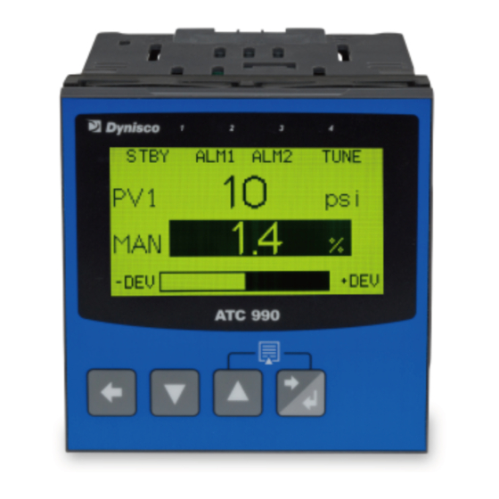
LED Function Labels Process Variable Value 1 Engineering Units Process Variable Value 2 Input as Percentage of Span Typical Operation Screen Subsequent screens allow the display and selection/adjustment* alarm status and trends. P/N: n/a Rev: n/a ECO: n/a www.dynisco.com -12-... - Page 13 Cursor Line Process Variable Trend PV Value At Cursor Line Setpoint Trend (dotted) Trend Lower Scale Value Time Markers (10 samples per marker) Sample Interval (or Time at Trend View Cursor Line) P/N: n/a Rev: n/a ECO: n/a www.dynisco.com -13-...
- Page 14 RPM) In automatic mode either mode is available (not at the same time) In manual mode a parameter is provided to select the first or second method of indication. P/N: n/a Rev: n/a ECO: n/a www.dynisco.com -14-...
- Page 15 When the input signal goes to zero the controller output reaches the saturation for integral factor effect; when the process restarts the controlled output will have an excessive and dangerous overshoot. P/N: n/a Rev: n/a ECO: n/a www.dynisco.com -15-...
- Page 16 Manual mode. Differential Pressure value: This is always to be calculated as A-B or pressure 1- pressure 2. Only available when controller has a 2nd Universal input card fitted. P/N: n/a Rev: n/a ECO: n/a www.dynisco.com -16-...
- Page 17 Pressure Tune Output Pulse Enter Value of maximum output pulse to be applied in Pressure tuning mode. Pressure standby Threshold Enter Value of required threshold that activates Standby by recover period from OFF P/N: n/a Rev: n/a ECO: n/a www.dynisco.com -17-...
- Page 18 If the Recorder Configuration menu is entered on an instrument without this option. Recording In Progress Warning If recording in progress when Recorder Configuration entered. - Access to the Start/ Stop or Abort screens only until the recording is stopped. P/N: n/a Rev: n/a ECO: n/a www.dynisco.com -18-...
- Page 19 *Both Recorder Trigger state and Digital input selection must be the same to start recording ** Applies to Temperature control Only not pressure control. P/N: n/a Rev: n/a ECO: n/a www.dynisco.com -19-...
- Page 20 If Supervisor Mode is configured (requires PC software), enter correct code number to continue. Default Value = 10 Supervisor Mode Screens … Press to select up to 50 Configuration parameters in turn. Follow on-screen prompts to alter the values. P/N: n/a Rev: n/a ECO: n/a www.dynisco.com -20-...
- Page 21 Start/Stop Data Recording Manually Stop, or Start a new recording. – if Log Trigger is Recorder Menu Start/Stop. Abort Recording Forces a recording to Stop, overriding the selected record trigger. – if P/N: n/a Rev: n/a ECO: n/a www.dynisco.com -21-...
- Page 22 CJC Enable/Disable Enables/disables internal Thermocouple Cold Junction Compensation. The default value is Enabled. Process Variable Offset Trims the PV. +Ve values add to, –Ve values subtract from measured input. Caution: Use with care! P/N: n/a Rev: n/a ECO: n/a www.dynisco.com -22-...
- Page 23 Enable/disable PID Control Outputs, Engage Pre Tune or self tune and Increments or decrement control output percentage . Strain Gauge Calibration Input n Shunt resistor Enabled or Disable Default : Enabled P/N: n/a Rev: n/a ECO: n/a www.dynisco.com -23-...
Need help?
Do you have a question about the ATC990 and is the answer not in the manual?
Questions and answers