
Related Manuals for Full Gauge Controls MULTIPOWER


Summary of Contents for Full Gauge Controls MULTIPOWER
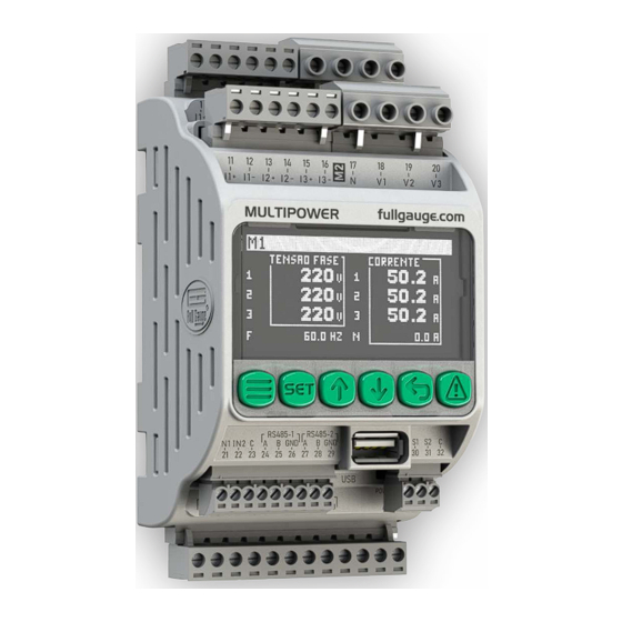
- Page 1 MULTIPOWER OLED Monitoring Electrical Graphic System magnitude meter display Alarms Datalogger Modbus Recipe protocol system Have this manual in the palm of your hand through the FG Finder app.
-
Page 2: Table Of Contents
1. SUMMARY............................................2 2. DESCRIPTION..........................................4 3. APPLICATIONS..........................................4 4. GLOSSARY............................................5 5. TECHNICAL SPECIFICATIONS.......................................6 6. ELECTRICAL PRECAUTIONS ......................................6 7.INSTALLING MULTIPOWER ....................................7 8. DIMENSIONS ...........................................7 9.CONNECTION DIAGRAM........................................8 9.1 BASIC CONNECTION TYPES ....................................9 9.1.1 1F + N SINGLE PHASE.....................................9 9.1.2 2F + N TWO-PHASE ......................................9 9.1.3 3F + N THREE PHASE.......................................9... - Page 3 1. SUMMARY 18.1.1 METERS .........................................36 18.1.2 ALARMS..........................................38 18.1.3 AUXILIARIES........................................39 18.1.4 EVENTS..........................................40 18.1.5 DATALOGGER ........................................42 18.1.6 DIGITAL INPUTS ......................................42 18.1.7 SENSORS........................................43 18.2 SYSTEM SETTINGS ..................................43 18.3 COMMUNICATION SETUP ................................43 18.4 DATA MANAGEMENT ....................................44 18.5 RESTORE FACTORY VALUES..................................44 19. ALARMS .............................................45 19.1 ALARM DISPLAY ....................................45 19.2 ALARM TABLES......................................46 19.2.1 SYSTEM ALARMS ....................................46 19.2.2 VOLTAGE AND CURRENT ALARMS CORRESPONDING TO METER M1 ..................46...
-
Page 4: Description
2. DESCRIPTION MULTIPOWER is a double three-phase power meter. Compact and versatile, it allows the measurement of three-phase, two-phase and single-phase circuits. In addition to that, it has a balanced circuit measurement mode, which provides cost and space savings, enabling a meter to estimate three different three-phase consumptions by measuring the current of a phase through a three-phase electrical circuit. -
Page 5: Glossary
4. GLOSSARY ŸActive power (W): Active power is that part of electrical power that is converted into useful work or other forms of power within an electrical circuit. It is the real power consumed or supplied by a device or system, responsible for carrying out mechanical, thermal, lighting work, among others. ŸReactive Power (VAR): Reactive power does not perform useful work directly but is necessary to maintain voltage and current in phase in alternating current circuits. -
Page 6: Technical Specifications
-The installation or maintenance of the product must only be carried out by qualified professionals. ACCESSORIES: -Use only original Full Gauge Controls accessories. -If in doubt, contact technical support. AS IT IS CONSTANTLY EVOLVING, FULL GAUGE CONTROLS RESERVES THE RIGHT TO CHANGE THE INFORMATION CONTAINED IN THE MANUAL AT ANY TIME WITHOUT PRIOR NOTICE. -
Page 7: Installing Multipower
To remove the controller from the DIN rail, use a suitably sized screwdriver to open the catch. 8. DIMENSIONS For more effective fixation of MULTIPOWER, it is important to pay attention to the product dimensions. 110,00 mm / 4,33" 138,65 mm / 5,46"... -
Page 8: Connection Diagram
9. CONNECTION DIAGRAM Load (CT)Current transformer positive (+) (-) negative Current meter Voltage meter Type 2 connector Type1 connector Load Voltage meter Current meter Type 2 connector Type 1 connector RS485-1 RS485-2 Type 3 connector Important : Check the purchased model Type 1 connector Relays Type 1 connector: For Type 1 (5.0mm) connectors... -
Page 9: Basic Connection Types
9. CONNECTION DIAGRAM 9.1Connection types: Meters M1 and M2 operate independently, their operating modes are defined by parameters 1.1.1 M1: operating mode, and 1.1.22 M2: operating mode, the available modes are: single-phase, two-phase, three-phase and three-phase balanced. 9.1.1 1F+N Single-phase: Reads one phase, the reading of the other phases is disabled. -
Page 10: N Three-Phase Balanced
9. CONNECTION DIAGRAM 9.1.4 3F+N Three-Phase Balanced: In the context of a balanced three-phase system, current measurement is performed on only one of the phases, with each phase representing an independent three-phase circuit. That is, phase 1 corresponds to circuit 1, phase 2 to circuit 2 and phase 3 to circuit 3. Power, demand, and power values are calculated by multiplying the voltage by the current of each phase and then multiplying this result by 3. -
Page 11: Installation Precautions
For the MULTIPOWER to correctly recognize the data on power consumed and supplied, it is necessary to pay attention to the installation of the primary and the polarity of the CT secondary. If the CT connection is made with reversed polarity, the MULTIPOWER will accumulate the consumed power in the supplied power records, and vice versa. -
Page 12: Navigation Keys
10. NAVIGATION KEYS To switch between screens, edit parameters, view advanced functions, and perform other tasks, the MULTIPOWER has 6 navigation keys on its front panel: SYMBOL DESCRIPTION Accesses the Main Menu and Control Menu. MENU Control Menu: Press the key Main Menu: Keep the key pressed for 2 seconds Confirms the editing of parameters and values. -
Page 13: Tela De Resumo
The summary screens display the main electrical measurements and power accumulators. Pressing the keys, you can navigate between them. The display mode is linked to the operating mode configured on the meters. By default, MULTIPOWER uses the disabled operating mode. The operating mode may be changed by accessing the Main Menu Settings Gauges. - Page 14 12. SUMMARY SCREEN When pressing , it display others values. ➊ ➋ ➎ ➍ ➌ ➏ ➐ ➑ ➊ ➎ Power display table. Displays the three electrical powers, Active power, Reactive power, Apparent power. ➋ ➏ Demand display table. Consumed power display table. ➌...
-
Page 15: N Two-Phase Operating Mode
12. SUMMARY SCREEN 12.3 2F + N operating mode Two-Phase: This mode of operation allows measurement in two phases, either between them or between each phase and the neutral. The summary screen displays quantities such as voltage, current, frequency, alarm signaling and meter identification. On the other screens, it is possible to view power and demand quantities, as well as the calculation of the power factor and the accumulators of consumed and supplied power. - Page 16 12. SUMMARY SCREEN In this mode of operation, power, demand, power consumed, and power supplied are displayed on screens separated by the total value and the value per measured phase. Total Power and Demand ➊ ➋ ➎ ➍ ➌ ➊ ➌...
- Page 17 12. SUMMARY SCREEN Consumed and supplied power ➊ ➋ ➌ ➊ ➌ Phase indication to be displayed: Power consumed table. M1 (Totals) M1 (Phase 1) M1 (Phase 2) ➋ Power supplied table. Consumed and supplied power Phase 1 Consumed and supplied power Phase 2...
-
Page 18: N 3F Full Operating Mode
12. SUMMARY SCREEN 12.4 3F + N Three-phase operating mode: This mode performs measurement using the three phases and the neutral. The summary screen displays quantities such as voltage, current, frequency, alarm signaling and meter identification. On the other screens, it is possible to view power quantities and active, reactive, and apparent demand, as well as the power factor and consumed and supplied power. - Page 19 12. SUMMARY SCREEN Total Power and Demand ➊ ➋ ➎ ➍ ➌ ➊ ➌ Phase indication to be displayed: Indicates whether Power Factor is capacitive or M1 (Totals) inductive: M1 (Phase 1) M1 (Phase 2) ➍ M1 (Phase 3) Displays power factor value. ➋...
- Page 20 12. SUMMARY SCREEN Consumed and supplied power ➊ ➋ ➌ ➊ ➌ Indication of the phase to be displayed: Shows the power consumed. M1 (Totals) M1 (Phase 1) M1 (Phase 2) M1 (Phase 3) ➋ Shows the power supplied. Consumed and supplied power Phase 1 Consumed and supplied power Phase 2 Consumed and supplied power Phase 3...
-
Page 21: Balanced Operating Mode
12.5 3F+N Balanced operating mode: As previously described, in item 9.1.4, in 3F + N Three-Phase Balanced mode, MULTIPOWER performs all power, demand and power calculations using values from just one phase of each load in a balanced three-phase circuit. However, the resulting values are presented on the summary screens multiplied by 3, and the summary screens do not display total values. - Page 22 12. SUMMARY SCREEN Here is an example of the calculation used to demonstrate the representation of powers in mode 3F + N Three-Phase Balanced: Power and Demand Phase 1 * For other values of active power, (S) = Voltage x Current reactive power, demand values, (S) = 220 x 50.2 x 3 consumed and supplied power, the...
-
Page 23: Control Menu
5 Clear records direction of active and reactive power flow, as well as the power Allows you to reset all records in MULTIPOWER or reset factor of the three phases. The coherence between the values of the 3 phases is an indication that the connection of the phases and records per interest groups, per meter or per phase. -
Page 24: Control Menu Screens
13. CONTROL MENU 13.2 Screens in the Control Menu: The following is a description of the screens displayed in the control menu options. 13.2.1 Access Control: Displays a screen where the advanced access code must be entered. Access control: Viewer access! Enter code: ➊... -
Page 25: Power Accumulators
13. CONTROL MENU 13.2.3 Power accumulators: key toggles the meter to be displayed. Displays the power accumulators of meters M1 and M2, per phase and total. Pressing ➊ 3.1 Power accumulator Phase 1 consumed ➋ active energy 350.0 KWh ➌ ➌... -
Page 26: Reset Records
13. CONTROL MENU 13.2.5 Clear records: On this screen it is possible to reset the minimum and maximum records, power accumulators and demand of the two meters. Through the keys, you can select the group of records to be reset by pressing the DDD key. Notes: You must enter the advanced access code (123), in access control. -
Page 27: Date And Time
13. CONTROL MENU 13.2.7 Date and time: This screen displays the current system date and time and allows you to adjust it. Data and Time: ➊ 08/07/23 10:45:50 ➋ Day: ➌ ➌ ➊ Date in day/month/year, and Time in hour: minutes: second Demonstration of value to be changed ➋... -
Page 28: Inputs And Outputs
13. CONTROL MENU 13.2.9 Inputs and outputs: This screen displays the status of all digital outputs, digital inputs, and sensor temperatures. Inputs and outputs ➊ ➏ O1: Off IN1:Off O2: Off IN2:On ➋ O3: Off O4: On S1: 21.6°c ➌ S2: 0.9°c ➎... -
Page 29: Consumed And Supplied Power
Power consumed and supplied: MULTIPOWER is a meter that operates in 4 quadrants, that is, it is capable of separately measuring and recording the power that is consumed or supplied to the electrical grid, also identifying whether the power factor is inductive or capacitive in both cases. -
Page 30: Modular And Angular Asymmetry
15. MODULAR AND ANGULAR ASYMMETRY Detection of modular/angular asymmetry alarms: Modular voltage asymmetry is quantified by analyzing the voltage amplitudes in each phase in relation to the nominal value (i.e., the standard line voltage of the electrical network). When the voltage amplitudes in the phases are not equal, there is a modular asymmetry. This is expressed in terms of percent imbalance and is calculated using the following formula: S = Sensitivity (0 to 100%) Modular asymmetry: Tolerance = (100 - S) x (Average of Measured Voltages) -
Page 31: Auxiliary Logic
16.1 Temperature Alarms: MULTIPOWER allows the configuration of up to two independent temperature alarm logics, where it is possible to assign an alarm output to each sensor or up to two alarm outputs in different ranges for the same sensor. It also allows linking with Auxiliaries in order to turn off their output in the event of an alarm. -
Page 32: Auxiliaries
16. AUXILIARY LOGIC 16.2 Auxiliaries: MULTIPOWER offers support for up to four auxiliary logic, which can be programmed to operate as thermostats or auxiliary outputs, depending on the auxiliary operating mode setting. 16.2.1 Always On Operating mode: In this mode, the auxiliary output is activated according to the time schedule of the linked events. -
Page 33: Cooling Thermostat Operating Mode
16. AUXILIARY LOGIC 16.2.3 Cooling Thermostat operating mode: In this mode, the Auxiliary operates as a heating thermostat, where the output is activated for values lower than the setpoint minus hysteresis and is turned off for values greater than the setpoint. The operation of the thermostat does not depend on the schedule of events. Example: 1.3.6 AUX2: Operating mode = Cooling thermostat... -
Page 34: Control Of The Auxiliary Status
After the time in manual mode has elapsed, the Auxiliary mode returns to the previous selection, off or automatic. 16.3 Events: MULTIPOWER allows the use of up to 8 configurable events where it is possible to program the performance of one or more auxiliaries according to the time schedule. -
Page 35: Main Menu
17. MAIN MENU To access the Main Menu, press the key and keep it pressed for at least 2 seconds. Main menu: 1.1 Func. Settings Function 1 Meters settings 2 Alarms 2 System settings 3 Auxiliaries 3 Communication 4 Events settings 5 Datalogger 4 Data Management... -
Page 36: Parameter Table
18. PARAMETER TABLE 18.1 Settings : In this option it is possible to change parameter values, according to the MULTIPOWER application. 18.1.1 Meters: Parameters relating to the configuration of meters M1 and M2. Function Description Maximun Standard Unit Minimun M1: Operation mode 1.1.1... - Page 37 18. PARAMETER TABLE 1.1.1 and 1.1.22 M1 and M2: Operating mode: Allows you to configure the meter for different operating modes. In single-phase mode, only phase 1 voltage and current are considered. In two-phase mode, the voltages, and currents of phases 1 and 2 are taken into account. In three-phase mode, the voltages, and currents of the three phases are considered, forming a single three-phase circuit.
-
Page 38: Alarms
18. PARAMETER TABLE 1.1.14 and 1.1.35 M1 and M2: Alarm inhibition delay: Period of time after meter energization in which alarm events are taken into account. 1.1.15 and 1.1.36 M1 and M2: Angular asymmetry sensitivity: Allows you to configure the sensitivity with which the meter detects angle asymmetry between. The higher the value of this parameter, the lower the error tolerance. -
Page 39: Auxiliaries
18. PARAMETER TABLE 1.2.1 and 1.2.9 AL1 and AL2: Low temperature: Temperature value below which the low temperature alarm is triggered. 1.2.2 and 1.2.10 AL1 and AL2: High temperature: Temperature value below which the high temperature alarm is triggered. 1.2.3 and 1.2.11 AL1 and AL2: Hysteresis: Allows you to configure the difference between the measured temperature and the alarm value to exit the alarm condition. -
Page 40: Events
18. PARAMETER TABLE Description Function Minimum Maximum Unit Standard AUX3: Temperature setpoint -50,0 200,0 1.3.14 °C 200,0 AUX3: Hysteresis °C 1.3.15 AUX3: Manual time 9999 minutes 1.3.16 AUX3: Temperature sensor 1.3.17 AUX3: Digital output 1.3.18 AUX4: Operating mode 1.3.19 AUX4: Temperature setpoint -50,0 200,0 50,0... - Page 41 18. PARAMETER TABLE Description Function Minimum Maximum Standard Unit Event 2: Days of the week 1.4.7 Event 2: Link 1.4.8 Event 3: Init time 1.4.9 00:00 23:59 12:00 hh:mm Event 3: End time 00:00 23:59: 12:00 hh:mm 1.4.10 Event 3: Days of the week 1.4.11 Event 3: Link 1.4.12...
-
Page 42: Datalogger
Indicates whether the controller should start writing new data to the beginning of the datalogger memory when it is full. This avoids losing the last data outputted by the equipment. If set to zero, when memory is full, the MULTIPOWER indicates memory full. -
Page 43: Sensors
Note: When ECO mode is active, a short press on any of the keys is enough to deactivate it. 18.3 Communication Setting: MULTIPOWER has two independently configurable RS-485 communication ports for communication with Sitrad software or supervisors that use the MODBUS protocol. -
Page 44: Data Management
(.rec). 4.3 Firmware update: Allows you to update the MULTIPOWER firmware. The file must be stored in the MULTIPOWER folder, and its name must have a maximum of 42 characters, including the extension (.ffg). 18.5 Restore factory defaults :... -
Page 45: Alarms
19. ALARMS MULTIPOWER has an alarm management system. The alarm settings are linked to the electrical quantities of the meters and the values of the temperature sensors and digital inputs. When an alarm occurs, an audible warning will be issued and will remain active until one of the following conditions occurs: - The alarm condition no longer occurs, and the alarm is not in manual reset condition. -
Page 46: Alarm Tables
Indicative alarm AL001 Blocking of control functions AL002 (Reset controller parameters) Blocking of control functions AL003 ECAL (Contact Full Gauge Controls) Indicative alarm AL004 Memory full Registration paused due to settings change Indicative alarm AL005 19.2.2 Alarms Voltage and current corresponding to the meter M1:... -
Page 47: Temperature Alarms
Gauge Controls instruments with Sitrad . Full Gauge offers different interface options, including technologies such as USB, Ethernet, Wifi, among others. For more information, consult Full Gauge Controls. Sold separately. MODBUS PROTOCOL The controller allows you to configure the RS-485 communication port for the MODBUS-RTU protocol. -
Page 48: Important
After this year with resellers, the guarantee will continue to be valid if the instrument is sent directly to Full Gauge Controls. This period is valid for the Brazilian market. Other countries have a 2 (two) year warranty. The products are guaranteed in case of manufacturing failure that makes them unsuitable or improper for the applications for which they are intended.
Need help?
Do you have a question about the MULTIPOWER and is the answer not in the manual?
Questions and answers