Advertisement
Quick Links
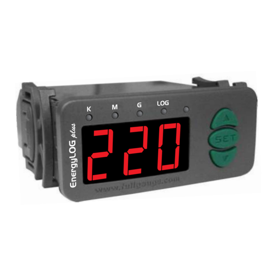
1 - DESCRIPTION
The Enë®gyLOG plus was developed for monitoring and displaying the electric energy quality and
consumption. It can be used in business or home applications. It has a real time clock and internal
memory to periodically store the electric network data measured and the user can configure the period
between measurements. The voltage/current True-RMS* measurement method allows the
Enë®gyLOG plus to calculate and display the active, reactive and apparent power, plus the power
factor and power supply frequency. Current up to 5A can be measured directly through the controller. A
current transformer (CT) is needed if you want to measure higher currents up to 1000A. Configuring the
Enë®gyLOG plus is easy and fast with the SITRAD software. Equally easy and fast is the access to
the data stored in device internal memory.
*True RMS: Is the real and effective voltage value which also includes the voltage generated by high
frequency noise in the distributing network (harmonic distortion). This is the actual voltage applied to the
connected load (example: electric motor, compressor). This method allows the precise voltage
measurement for any type of wave form. Other measurement methods give correct value of applied
voltage only for perfect sine wave forms.
2 - APPLICATIONS
• Monitoring and displaying the energy quality and consumption for single-phase electrical installations.
3 - TECHNICAL SPECIFICATIONS
- Power Supply: 90 - 264Vac (50/60 Hz)
- Monitored Voltage: 80 to 280Vac (different versions for 50 or 60Hz)
- Monitored Current: 0 to 5A without CT and 0 to 1000A with CT*
- Dimensions: 71 x 28 x 71mm (2,8" x 1,103" x 2,8")
- Operation temperature: 0° to 50°C (32° to 122°F)
- Operation humidity: 10 to 90% RH (without condensation)
- Resolution:
Voltage: 1Vac for the whole range
Current: 0.01A between 0 and 10A
0.1A between 10A and 100A
1A between 100A and 1000A
Apparent Power (also valid for Active Power,
in W, and Positive Reactive Power in VAr):
0.01VA between 0 and 10VA
0.1VA between 10VA and 100VA
1VA between 100VA and 1000VA
10VA between 1kVA and 10kVA
100VA between 10kVA and 100kVA
1kVA between 100kVA and 280kVA
Negative Reactive Power (Capacitive power
factor, see item 7.2):
0.1VAr between 0 and -10VAr
1VAr between -10VAr and -100 VAr
100VAr between -100VAr and -10kVAr
1kVAr between-10kVAr and -100kVAr
100kVAr between -100k and -280kVAr
*The stability of the current transformer has a direct effect on the measured readings
4 - CONFIGURATIONS
4.1 - To enter the function menu
Press
and
simultaneously for 2 seconds to display
displayed, press
(shortly), and enter the code (123) through the
SET
confirm. Use the
and
keys to access the other functions and proceed the same way to adjust
them. Press
(long touch) until
SET
4.2 - Functions
To enter the access code
Advanced setting functions
Date and time setting
4.3 - Parameters table
Fun
Description
Default display parameter
P rimary CT winding current
Datalogger operation mode
Datalogger sampling interval
Record data when error occur
Overwrite data in the memory when it is full
Network equipment address RS - 485
Enë®gyLOG plus
FOR MONITORING AND DISPLAYING THE
ELECTRIC ENERGY QUALITY AND
CONSUMPTION
Ver.01
®
Energy: 0.01VAh between 0 and 10VAh
0.1VAh between 10VAh and 100VAh
1VAh between 100VAh and 1000VAh
10VAh between 1kVAh and 10kVAh
100VAh between 10kVAh and 100kVAh
1kVAh between 100kVAh and 1000kVAh
10kVAh between 1MVAh and 10MVAh
100kVAh between 10MVAh and 100MVAh
1MVAh between 100MVAh and 1000MVAh
10MVAh between 1GVAh and 10GVAh
100MVAh between 10GVAh and 100GVAh
1GVAh between 100GVAh and 999GVAh
and release the keys. When
and
keys. Press
is displayed to exit the menu and return to normal operation.
Min.
Max.
0
7
5
1000
Amperes
0
2
5
999
Seconds
1-yes
0-no
0-no
1-yes
1
247
5 - PARAMETERS DESCRIPTION
Default display parameter
The user can select the parameter to be displayed as default from the options below:
Primary CT winding current:
This allows you to configure the settings for the transformer that will be used with the
EnergyLOG plus
of 5 A. If you wish to measure currents up to 5 A you don't need to use the current transformer; in this
case you just need to configure the function with the value 5 and connect your controller directly to the
load.
Datalogger operation mode:
This indicates how the data storage device operates:
Datalogger sampling interval:
Time period in which the controller will register a sample of the electric network.
Record data when error occur
It indicates whether any errors in the meter will force the recording of data in memory regardless of
sampling interva
Overwrite data in the memory when it is full
This allows you to start overwriting data from datalogger memory beginning when the memory is full.
This prevents the latest data recorded from equipment being erased first.
Network equipment address RS-485:
This is the device address for communication with Sitrad software. Note: You cannot have two or more
devices with the same address in the network.
6 - EASY ACCESS FUNCTIONS
6.1 - Viewing current date and time:
You can press the
shows the current day, month, year, hours and minutes, in this order.
Ex: 03/17/2006 12h43min
6.2 - Viewing other functions:
is
To switch among the other data of energy and power press
follows:
to
SET
The selected information will be displayed during 15 seconds. The display returns then to the parameter
selected in F01 (default display parameter).
Unit
Default
-
0
6.3 - Clearing datalogger memory:
5
Press the
-
2
don't want to clear the memory and cancel the operation press
5
is displayed and press
-
1-yes
-
1-yes
6.4 - Manual datalogger activation:
-
1
With
internal recording (datalogger) ON or OF . The
(datalogger
If the parameter
be displayed accordingly. The operation of the datalogger is indicated by LED "LOG" at the top of the
diplay.
Voltage
Current
Apparent Power
Active Power
Reactive Power
Power Factor
Consumption of energy (in the period)
Mains Frequency
. Select the primary winding current that will produce a secondary winding current
Always OFF
Always ON
Manual Operation
set in F0 .
4
l
key shortly to view the date and time set in the controller. The display
SET
Day
Month
Year
Hours
Minutes
Voltage
Current
Apparent power
Active power
Reactive power
Power factor
Consumption of energy measured by the device
Mains Frequency
and
keys for 2 seconds to display
SET
to confirm and exit the function.
SET
configured as
and pressing the
SET
F
message is displayed followed by the message
) or
(datalogger
is configured with the values
®
to display the desired data code, as
. The LCD then displays
. If you
. To clear the memory press
until
SET
key for 2 second, y
ou can turn the voltage data
).
or
the messages
or
will
Advertisement

Related Manuals for Full Gauge Controls EnergyLOG plus


Summary of Contents for Full Gauge Controls EnergyLOG plus
- Page 1 Other measurement methods give correct value of applied This allows you to configure the settings for the transformer that will be used with the EnergyLOG plus voltage only for perfect sine wave forms.
- Page 2 7.1 - Indication 3: Install transient suppresors (RC filters) parallel to the loads as to increase the product life of the The EnergyLOG plus has 4 indicator leds in the upper part. The leds K, M and G are used to relays.
Need help?
Do you have a question about the EnergyLOG plus and is the answer not in the manual?
Questions and answers