Advertisement
Quick Links
Have this manualin your hands
using the FG Finder app.
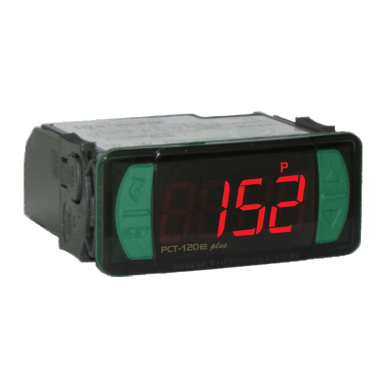
1. DESCRIPTION
The PCT-120e plus is an easy to install and operate two-stage pressure controller designed for
systems that require effective pressure control. Operating in pressurization, despressurization,
refrigeration, heating or alarm mode, it directly controls loads of up to 1HP. It also has digital inputs that
allow external devices to be used for protecting the controller system, hourmeters that store the number
of hours compressors/pumps are operating and indicate when maintanance should be performed on
them. Operating in combination with temperature sensors, it also performs dynamic and adiabatic
condensation control, dynamic evaporation, superheating and subcooling monitoring, promoting
greater energy efficiency in the system. It also has serial output for communication with Sitrad and an
intelligent locking function, preventing unauthorized persons from changing the control parameters.
2. APPLICATIONS
Control over suction or discharge in refrigeration systems, air compressors, semi-artesian pumps,
•
water tanks and filters, superheating and subcooling monitoring.
3. TECHNICAL SPECIFICATIONS
PCT-120E Plus:
Power supply
PCT-120EL Plus 12Vac/dc:
PCT-120EL Plus 24Vac/dc:
Pressure control range
Temperature control range
Water level control range
Approximate consumption
Sensors available for acquisition
Pressure resolution
Temperature resolution
Water level resolution
Operating temperature
Maximum current
Operating humidity
Digital Inputs
Protection level
Product dimensions
Dimensions of the clip for fixing the instrument
4. INDICATORS AND KEYS
Led indicator (output 2 on/off)
Led indicator (output 1 on/off)
Quick Access
2
Menu key
Set key
e plus
PCT-120
5.1INSTALLATION - ELECTRIC CONNECTIONS
SITRAD
GND
P1
P2
Electrical connection of temperature
sensors/digital inputs:
D1/T1: Pins 4-8
D2/T2: Pins 7-8
PCT-120
DIGITAL PRESSURE CONTROLLER
AND INDICATOR
Functions
Control
Serial
Lock
Functions
Programming
Shutdown
90~240Vac (50/60 Hz)
12Vac/dc 10% (50/60 Hz)
24Vac/dc 10% (50/60 Hz)
-14 to 850 psi / -1 to 58.6 bar (configurable sensor
operating range)
-50 to 200°C / -58 to 392°F
0 to 250 mwc (configurable sensor operating range)
±
4VA
SB69 - 100A* (0 to 100 psi / 0 to 6,9 bar)
SB69 - 200A* (0 to 200 psi / 0 to 13,8 bar)
SB69 - 500A* (0 to 500 psi / 0 to 34,4 bar)
SB69 - 850A* (0 to 850 psi / 0 to 58,7 bar)
SB70* - (-50 to 105°C / -58 to 221°F)
SB59* - (-50 to 200°C / -58 to 392°F)
*Sensors sold separately
1 psi / 0,1 bar
0,1°C / 1°F
0,1 mwc
0 to 60°C / 32 to 140°F
OUT1: 16A / 1HP 250Vac
OUT2: 16A / 1HP 250Vac
10 to 90% UR (no condensation)
Configurable dry contact
IP 65 (frontal)
76 x 34 x 77 mm (W x H x D) (2,99 x 1,33 x 3,03'')
±
±
71 0,5 x 29 0,5 mm (2,80 x 0,01 x 1,14 x 0,01'')
Water level unit indication LED (mwc)
Temperature unit indication LED
Led indicator (pressure units: psi/bar)
P B
m
Upper key
Lower key
90~240 Vac Connection
e plus
PCT-120
16A 1HP
16A 1HP
Electrical connection of pressure
sensors:
Brown: 12 Vdc
Green or White: 4~20 mA
e plus
IP 65
FRONT
Supervisory
Protection
Hourmeter
System
Level
5. INSTALLATIONS - PANEL AND ELECTRIC CONNECTIONS
WARNING
FOR INSTALLATIONS THAT REQUIRE WATER TIGHTNESS, THE OPENING TO INSTALL THE CONTROLLER MUST BE 71,5 x 29,5 mm
(28,15 x 11,6 in) MAXIMUM. THE SIDE LATCHES MUST BE FIXED SO THAT THEY PRESS THE SEALING GASKET TO PREVENT
INFILTRATION BETWEEN THE OPENING AND THE CONTROLLER.
IMPORTANT
IT IS ESSENTIAL TO USE THE CORRECT TOOLS IN ORDER TO AVOID DAMAGES TO THE INSTRUMENT'S CONNECTION
TERMINALS:
2.4 mm (3/32'') SLOTTED SCREWDRIVER FOR ADJUSTMENTS IN THE SIGNAL TERMINALS;
PHILLIPS SCREWDRIVER #1 FOR ADJUSTMENTS AT THE POWER TERMINALS.
6. OPERATIONS
6.1 Quick Access Menu Map
To access or browse the quick access menu, use the ;key (quick touch) while the controller is displaying the pressure.
Each touch displays the next function in the list; to confirm, use the /key (quick touch)
PRESSURE ADJUSTMENT
(SETPOINT)
;
DIFFERENTIAL ADJUSTMENT
(HYSTERESIS)
;
HOURMETER VIEW
;
RESET OF THE HOURMETER
;
90~240Vac
e plu s
e plu s
PC T- 12 0
PC T- 12 0
Panel
(side view)
EXIT FUNCTION
FUNCTION SELECTION
CONTROL FUNCTIONS
(ON/OFF)
FUNCTIONS LOCK
12 Vac/dc Connection
el
SITRAD
PCT-120
plus 12v
GND
16A 1HP
16A 1HP
12Vac/dc
P1
P2
24 Vac/dc Connection
SITRAD
el
PCT-120
plus 24v
GND
16A 1HP
16A 1HP
24Vac/dc
P1
P2
evolution
71
± 0,5
mm
(2,80 0,01'')
±
Dimensions of the clip
for fixing the instrument
Panel (front view)
;
;
;
;
Power supply
Power supply
Advertisement

Related Manuals for Full Gauge Controls PCT-120E plus


Summary of Contents for Full Gauge Controls PCT-120E plus
- Page 1 1. DESCRIPTION 5. INSTALLATIONS - PANEL AND ELECTRIC CONNECTIONS The PCT-120e plus is an easy to install and operate two-stage pressure controller designed for systems that require effective pressure control. Operating in pressurization, despressurization, refrigeration, heating or alarm mode, it directly controls loads of up to 1HP. It also has digital inputs that ±...
- Page 2 6.2 Quick access keys map 6.3.4 Minimum and Maximum Records Pressing the <(quick touch) key while the pressure/temperature is displayed will show the message When the controller is displaying the standard screen, the following keys can be used as shortcuts for [rEg,] and then the minimum pressure/temperature and maximum pressure/temperature recorded.
-
Page 3: Description Of The Parameters
PSI / °C BAR / °F Description Default Default Unit Unit [,F13] High pressure in transducer P1 alarm -0,9 58,6 58,6 [,F14] OUT1 temperature setpoint °C -58,0 °F [,F15] Temperature control differential (Hysteresis) OUT1 20,0 °C °F [,F16] Minimum temperature setpoint allowed for the end user OUT1 °C -58,0 °F... -
Page 4: Water Tank
F04 - 1st stage operation mode (OUT1): F23 - Maximum output operating time OUT1 for maintenance (hourmeter): [,,,0]- Depressurization Whenever the output is activated the apparatus will count its operating time. When the counted time is [,,,1]- Pressurization equal or longer than the one set in this function, the display will show the message [Man1], signaling [,,,2]- Cooling that the compressor/pump must be serviced. - Page 5 F37 - 2nd stage operation mode (OUT2): F58 - Operating mode of the digital input 1: [,,,0]- Depressurization It allows choosing the operating mode of the digital input 1. [,,,1]- Pressurization [,,,0]- Disable [,,,2]- Cooling [,,,1]- Temperature sensor 1 [,,,3]- Heating [,,,2]- Enables 1st stage control (OUT1) (external switch, N.O.
- Page 6 F67 - Subcooling calculation: F77 - Time for functions lock: The subcooling control indicates how much cooling fluid is colder than the condensing temperature Allows control functions lock (see item 6.3.2). [,,15]- [,,60] - Defines the time in seconds for the controller to activate. needed to prevent loss of performance by evaporating the cooling fluid prior to the expansion valve.
-
Page 7: Environmental Information
It protects the product when the installation site is washed. Extension Frame The Full Gauge Controls extension frame allows the installation of Evolution and Ri line controllers with maximum measures of 76x34x77mm (2,99x1,31x3,03'’) (dimensions of the clipping for fixing in the extension frame are 71x29mm (2,80x1,14)) in varied situations, as it eliminates precision cut to embed the instrument.
Need help?
Do you have a question about the PCT-120E plus and is the answer not in the manual?
Questions and answers