
Related Manuals for AHS Antriebstechnik TSR70


Summary of Contents for AHS Antriebstechnik TSR70
- Page 1 MA-TSR70-ENN v1.0 TSR70 Manual Step motor drives TSR70 AHS Antriebstechnik GmbH Fichtenweg 17 64319 Pfungstadt Phone: +49 6157 9866110 Fax: +49 6157 9866112...
- Page 2 © AHS Antriebstechnik GmbH, 2023 No part of this documentation may be reproduced, processed or distributed in any form without the written permission of AHS Antriebstechnik GmbH. Errors excepted! We reserve the right to make changes to the content of the documentation and technical changes to...
-
Page 3: Table Of Contents
MA-TSR70-ENN Manual TSR70 Page 3 of 30 TSR70 Table of contents General ....................... 5 About this manual ........................5 Characteristics and modes of operation ................5 Warning and note icons ......................6 Safety ........................7 Important safety notes ......................7 Intended use .......................... - Page 4 MA-TSR70-ENN Manual TSR70 Page 4 of 30 TSR70 13.1 Dismantle ..........................29 13.2 Repair ........................... 30 13.3 Disposal..........................30 Order code ......................30 Status: 08/2023. More information under: www.ahs-antriebstechnik.de Technische Änderungen vorbehalten / Specifications are subject to change without notice...
-
Page 5: General
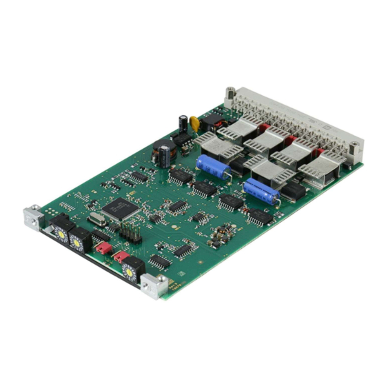
The unit parameters are set via two rotary switches and two jumpers on the front of the unit. A two-colour LED indicates the status of the unit by its colours and flashing signals. The TSR70 step motor dreives are designed in Eurocard format as plug-in units with a VG strip (DIN 41612). -
Page 6: Warning And Note Icons
MA-TSR70-ENN Manual TSR70 Page 6 of 30 TSR70 1.3 Warning and note icons The following warning and note icons are used in this manual: Icon Meaning Warning against a hazard which may cause heavy injury or death. Observe instructions to avoid hazards! Warning against a hazard which may cause slight injury. -
Page 7: Safety
This chapter contains important information for the safe use of the TSR70 step motor drive. As the machine manufacturer, you are responsible for the use of the TSR70 steo motor drive in your machine. AHS Antriebstechnik GmbH is not liable for damage caused by improper use of the TSR70 step motor drive. -
Page 8: Intended Use
TSR70 2.2 Intended use Use of the TSR70 step motor drives is only permitted in accordance with points (1) to (7) specified here. (1) The step motor drives of the TSR70 are intended for installation in electrical systems or machines and may only be put into operation as integrated components of systems or machines. -
Page 9: Product Identification
Page 9 of 30 TSR70 Product identification All versions of the TSR70 step motor drives are clearly identified by the type designation (order designation). The type designation and other information can be found on the type plate of the unit. 3.1 Type plate The type plate is attached to the black cover that covers the underside of the circuit board. -
Page 10: Technical Data
MA-TSR70-ENN Manual TSR70 Page 10 of 30 TSR70 Technical data 4.1 Electric data Supply voltage 24 - 75 V Motor current 0,9 to 6,3 A + 30 % with boost Number of selectable values Motor current @ ambient temperature 3,2 A @ 25 °C 1,6 A @ 45 °C... -
Page 11: Mechanical Data
TSR70 4.2 Mechanical data The step motor drive TSR70 consists of two or three parts, depending on the version. The printed circuit board, a lower black cover on which the type plate is attached and optionally an upper light- coloured cover. The covers are made of plastic. -
Page 12: Mechanical Installation
5.1 Switchbord assembly The step motor drive TSR70 is usually mounted as a plug-in unit in a subrack (e.g. 19 inch rack). The electrical connection is made completely via the 32-pole VG strip. Observe the following requirements for assembly: ... - Page 13 With forced ventilation 45 °C 3,5 A Check the heat sink temperature of the TSR70 by directly measuring it with a temperature sensor while the unit is running. In addition, the unit temperature is recorded via a sensor installed on the circuit board.
-
Page 14: Electrical Installation
The step motor drive may be installed only by specialist staff trained in electrical engineering. The TSR70 step motor drive has the 32-pin VG connector as its only connection element. The following section describes the pin assignment and typical wiring. -
Page 15: Pin Assignment
The pin assignment of the VG-strip connector is compatible with the DSR92- 70 step motor drive and other step motor drives. The pin assignment of the TSR70 can be found in the following labelled illustration or in the tables on the following pages: 6.2 Signal inputs/outputs... -
Page 16: Supply Voltage
In order for the TSR70 to be able to absorb the current in pulse form from the charging capacitor of the power supply unit or from an external backup capacitor, the cable length between the charging or backup capacitor and the TSR70 must not be too long (<= 1 m). - Page 17 Earth the shielding over a large area with shield clamps. The cable between the charging capacitor of the power supply unit and the TSR70 must not be longer than 1 m. If the cable is longer, an external back-up capacitor must be installed.
-
Page 18: Motor Connection
Motor phase 2 a26, c26, a28, c28 When connecting a 2-phase stepper motor to the TSR70 step motor drive, the following specifications must be observed: Use cables with a cross-section of 1.0 mm² to 1.5 mm². -
Page 19: Parameter Settings
MA-TSR70-ENN Manual TSR70 Page 19 of 30 TSR70 Parameter settings To adapt to different stepper motors and applications, the following parameters can be set on the TSR70 step motor drive: Motor current Step resolution Current reduction at standstill (motor current and waiting time) ... -
Page 20: Motor Current And Current Reduction At Standstill
If the rated nominal motor current is exceeded, this can lead to destruction of the motor due to demagnetisation or thermal overload. Set the output current of the TSR70 step motor drive to no more than the value of the rated motor current. Status: 08/2023. More information under: www.ahs-antriebstechnik.de... -
Page 21: Step Resolution
MA-TSR70-ENN Manual TSR70 Page 21 of 30 TSR70 7.2 Step resolution The step resolution is set with the rotary switch S3 according to the following table: Switch position Resolution decimal Resolution binary 1000 1600 2000 3200 5000 6400 10000 12800... -
Page 22: Operating Display: Status Led
Manual TSR70 Page 22 of 30 TSR70 Operating display: Status LED The TSR70 step motor drive has a two-colour LED on the front panel to display information about the operating status. These are to be interpreted as follows: Status LED... -
Page 23: Operatin Mode: Clock And Direction Of Rotation
direction of rotation signal The motor current is switched on immediately after the step motor drive TSR70 is ready for operation, unless the Disenergize input is active. The clock pulses and the direction of rotation signal are generated by an external clock generator. With each incoming clock pulse, the TSR70 rotates the motor one step further. -
Page 24: Commissioning
If the rated motor current is exceeded, this can lead to destruction of the motor due to demagnetisation or thermal overload. Set the output current of the TSR70 step motor drive to no more than the value of the rated motor current. Status: 08/2023. More information under: www.ahs-antriebstechnik.de... -
Page 25: Commissioning With Clock And Direction Signal
TSR70 10.1 Commissioning with clock and direction signal Requirement The machine or system is prepared for the installation of the TSR70 (chapter 5 Mechanical installation). The electrical wiring is prepared for the connection of the TSR70 (chapter 6 Electrical installation). -
Page 26: Debugging
TSR70 Debugging The TSR70 step motor drive switches off for its own protection if an error condition is detected due to internal measured variables. The two-colour LED on the front of the unit indicates the error number by a flashing code (chapter 8 Operating display). The colour of the two-colour LED changes to red. -
Page 27: Faulty Behaviour
The LED display lights up green (or flashes yellow). The motor has no torque. The TSR70 is enabled (and the drive signals are detected), but too little or no motor current is flowing. Check the cables for the supply voltage and the motor. - Page 28 The motor does not reach the expected position. Check whether the step size set on the TSR70 corresponds to the step size to which your controller is parameterised. Check whether the motor stops or loses steps because it is overloaded by too high acceleration or load torque.
-
Page 29: Maintenance And Cleaning
High electrical voltages can give people a dangerous electric shock. Measure the voltage at the supply voltage connection of the TSR70 and wait until the voltage has dropped below 24 V before touching the electrical connections of the step motor drive. - Page 30 The step motor drive TSR70 may only be repaired by authorised workshops or by the manufacturer. Any other repair attempts will invalidate the warranty. If you are a customer of a machine manufacturer in whose machine the step motor drive TSR70 is used, please contact the machine manufacturer first for repair.
Need help?
Do you have a question about the TSR70 and is the answer not in the manual?
Questions and answers