Table of Contents
Advertisement
Quick Links
Advertisement
Table of Contents

Related Manuals for Airlink101 AR315W


Summary of Contents for Airlink101 AR315W
- Page 1 802.11g Wireless Router Model # AR315W User’s Manual Ver. 2A...
-
Page 2: Table Of Contents
Table of Contents CHAPTER 1 INTRODUCTION ... 4 Wireless Router Features ... 4 Package Contents ... 6 Physical Details... 7 CHAPTER 2 INSTALLATION... 9 Requirements... 9 Procedure ... 9 CHAPTER 3 SETUP ... 13 Overview ... 13 Configuration Program ... 15 Setup Wizard ... - Page 3 Wireless Access ... 82 APPENDIX B ABOUT WIRELESS LANS... 84 Modes ... 84 BSS/ESS... 84 Channels... 85 WEP... 85 Wireless LAN Configuration... 85 APPENDIX C SPECIFICATIONS ... 86 Multi-Function Wireless Router ... 86 Wireless Interface... 86 Regulatory Approvals ... 87 APPENDIX D ...
-
Page 4: Chapter 1 Introduction
Chapter 1 Introduction This chapter provides an overview of the Wireless Router's features and capabilities. Congratulations on the purchase of your new Wireless Router. The Wireless Router is a multi- function device providing the following services: • Shared Broadband Internet Access •... -
Page 5: Wireless Features
• Multi-DMZ. For each WAN (Internet) IP address allocated to you, one (1) PC on your local LAN can be configured to allow unrestricted 2-way communication with Servers or individual users on the Internet. This provides the ability to run programs that are incom- patible with Firewalls. -
Page 6: Security Features
• UPnP Support. UPnP (Universal Plug and Play) allows automatic discovery and con- figuration of the Wireless Router. UPnP is by supported by Windows ME, XP, or later. Security Features • Password - protected Configuration prevent unauthorized users from modifying the configuration data and settings. •... -
Page 7: Physical Details
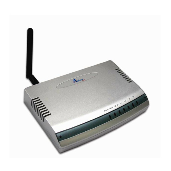
Physical Details Front-mounted LEDs Figure 1: Front Panel Power LED On - Power on. Off - No power. WAN LED On - Connection to the Broadband Modem attached to the WAN (Inter- net) port is established. Off - No connection to the Broadband Modem. Flashing - Data is being transmitted or received via the WAN port. -
Page 8: Rear Panel
Rear Panel Connect the supplied power adapter here. Power port LAN port Use standard LAN cables (RJ45 connectors) to connect your PCs to these ports. (10/100BaseT) If required, any port can be connected to another hub. Any LAN port will automatically function as an "Uplink" port when necessary. Connect the DSL or Cable Modem here. -
Page 9: Chapter 2 Installation
Chapter 2 Installation This chapter covers the physical installation of the Wireless Router. Requirements • Network cables. Use standard 10/100BaseT network (UTP) cables with RJ45 connectors. • TCP/IP protocol must be installed on all PCs. • For Internet Access, an Internet Access account with an ISP, and either of a DSL or Cable modem (for WAN port usage) •... -
Page 10: Verify Connection To Router
Step 1 Connect one end of a network cable to the WAN port of the router and connect the other end of the cable to the DSL/Cable modem. Step 2 With another network cable, connect one end of the cable to your computer’s network card and connect the other end to one of the LAN ports of the router. - Page 11 Step 5 After the IP address is released, type ipconfig/renew and press Enter. You should get an IP address of 192.168.1.x (where x is a number between 2 - 254). Proceed to Section 3, Configuring the Router. If you don’t get an IP address, reset the router by holding in the reset button at the back of the router for 10 seconds while it is ON and try ipconfig/renew again.
- Page 12 For Windows 95/98/ME Step 4 Go to Start, Run, type winipcfg and click OK. Step 5 Select your network card from the drop-down menu and click Release. Step 6 After the IP address is released, click Renew. You should get an IP address of 192.168.1.x (where x is a number between 2 - 254).
-
Page 13: Chapter 3 Setup
Chapter 3 Setup This chapter provides Setup details of the Wireless Router. Overview This chapter describes the setup procedure for: • Internet Access • LAN configuration • Wireless setup • Assigning a Password to protect the configuration data. PCs on your local LAN may also require configuration. For details, see Chapter 4 - PC Con- figuration. - Page 14 Use any of the following Administration Configuration settings or features: • Config File download/upload • Logs • Network Diagnostics (Ping, DNS Lookup) • Options (Backup DNS, TFTP, UPnP, Firewall) • PC Database • Remote Management • Routing (RIP and static Routing) •...
-
Page 15: Configuration Program
Configuration Program The Wireless Router contains an HTTP server. This enables you to connect to it, and configure it, using your Web Browser. Your Browser must support JavaScript. The configuration program has been tested on the following browsers: • Netscape V4.08 or later •... -
Page 16: Setup Wizard
Setup Wizard Step 1 Click Setup Wizard at the router’s main screen. Step 2 Click Next at the Setup Wizard. Step 3 Select your type of Internet Access. If you are not sure what type of connection you have, please contact your Internet Service Provider (ISP) for assistance. - Page 17 For Cable Modem Users: Step 4a Click on Clone MAC Address, click OK, then click Next. Proceed to Step For DSL Users: Step 4b For most DSL users, select PPPoE and click Next. Otherwise, choose your Login procedure for connecting to the Internet. Step 4c For PPPoE users, enter your Username and Password required to get online and click Next.
- Page 18 Step 5 Choose your IP Address assignment and click Next. For most users, you can use the default settings (Dynamic IP Address). If you are using a Static IP assigned by your ISP, select Specified IP Address and enter the applicable values. Step 6 Make sure the Test Internet Connection box is checked and click Finish then OK to begin the Internet Connection Test.
-
Page 19: Home Screen
Home Screen After closing the Setup Wizard, you will see the Home screen. Navigation & Data Input • Use the menu bar on the left of the screen, and the "Back" button on your Browser, for navigation. • Changing to another screen without clicking "Save" does NOT save any changes you may have made. -
Page 20: Lan Screen
LAN Screen Use the LAN link on the main menu to reach the LAN screen. An example screen is shown below. Data - LAN Screen TCP/IP IP Address IP address for the Wireless Router, as seen from the local LAN. Use the default value unless the address is already in use or your LAN is using a different IP address range. - Page 21 DHCP What DHCP Does A DHCP (Dynamic Host Configuration Protocol) Server allocates a valid IP address to a DHCP Client (PC or device) upon request. • The client request is made when the client device starts up (boots). • The DHCP Server provides the Gateway and DNS addresses to the client, as well as allocating an IP Address.
-
Page 22: Wireless Screen
Wireless Screen The Wireless Router's settings must match the other Wireless stations. Note that the Wireless Router will automatically accept both 802.11b and 802.11g connec- tions, and no configuration is required for this feature. To change the Wireless Router's default settings for the Wireless Router feature, use the Wireless link on the main menu to reach the Wireless screen. - Page 23 Options Mode Select the desired mode: • g & b - Both 802.11.g and 802.11b Wireless stations will be able to use the Wireless Router. • g only - Only 802.11g Wireless stations can use the Wireless Router. • b only - Only 802.11b connections are available. 802.11g Wire- less Stations will only be able to use the Wireless Router if they are fully backward compatible with the 802.11b standard.
-
Page 24: Wireless Security Screen
Wireless Security Screen This screen is accessed by clicking the "Configure" button on the Wireless screen. System Security Select the desired option, and then enter the settings for the selected method: System: • Disabled - No security is used. Anyone using the correct SSID can connect to your network. -
Page 25: Wep Screen
WEP Screen Select WEP from the drop-down menu. Authentica- Select the appropriate value for your wireless network - "Open System,” tion “Shared Key," or “Auto.” Default is Open System. Data Select the WEP Encryption level: Key Size • 64-bit (sometimes called 40-bit) encryption •... - Page 26 WPA Screen Select WPA-PSK from the drop-down menu. WPA – PSK Enter the pre-shared key here. Data is encrypted using a key derived from the network key. Other Wireless Stations must use the same network key. The PSK must be from 8 to 63 characters in length. Key Lifetime This determines how often the encryption key is changed.
-
Page 27: Password Screen
Password Screen The password screen allows you to assign a password to the Wireless Router. Once you have assigned a password to the Wireless Router (on the Password screen above) you will be prompted for the password when you connect, as shown below. -
Page 28: Chapter 4 Pc Configuration
Chapter 4 PC Configuration This chapter details the PC Configuration required on the local ("Internal") LAN. Overview For each PC, the following may need to be configured: • TCP/IP network settings • Internet Access configuration • Wireless configuration Windows Clients This section describes how to configure Windows clients for Internet access via the Wireless Router. - Page 29 PC Configuration Checking TCP/IP Settings - Windows 9x/ME: 1. Select Control Panel - Network. You should see a screen like the following: 2. Select the TCP/IP protocol for your network card. 3. Click on the Properties button. You should then see a screen like the following. Ensure your TCP/IP settings are correct, as follows: Using DHCP To use DHCP, select the radio button Obtain an IP Address automatically.
- Page 30 • On the Gateway tab, enter the Wireless Router's IP address in the New Gateway field and click Add, as shown below. Your LAN administrator can advise you of the IP Address they assigned to the Wireless Router. • On the DNS Configuration tab, ensure Enable DNS is selected. If the DNS Server Search Order list is empty, enter the DNS address provided by your ISP in the fields beside the Add button, then click Add.
- Page 31 PC Configuration Checking TCP/IP Settings - Windows NT4.0 1. Select Control Panel - Network, and, on the Protocols tab, select the TCP/IP protocol, as shown below. 2. Click the Properties button to see a screen like the one below.
-
Page 32: Obtain An Ip Address From A Dhcp Server
3. Select the network card for your LAN. 4. Select the appropriate radio button - Obtain an IP address from a DHCP Server or Specify an IP Address, as explained below. Obtain an IP address from a DHCP Server This is the default Windows setting. Using this is recommended. By default, the Wireless Router will act as a DHCP Server. -
Page 33: Checking Tcp/Ip Settings - Windows 2000
PC Configuration Checking TCP/IP Settings - Windows 2000: 1. Select Control Panel - Network and Dial-up Connection. 2. Right - click the Local Area Connection icon and select Properties. You should see a screen like the following: Figure 3: Network Configuration (Win 2000) 3. - Page 34 5. Ensure your TCP/IP settings are correct, as described below. Using DHCP To use DHCP, select the radio button Obtain an IP Address automatically. This is the default Windows setting. Using this is recommended. By default, the Wireless Router will act as a DHCP Server.
-
Page 35: Checking Tcp/Ip Settings - Windows Xp
PC Configuration Checking TCP/IP Settings - Windows XP 1. Select Control Panel - Network Connection. 2. Right click the Local Area Connection and choose Properties. You should see a screen like the following: 3. Select the TCP/IP protocol for your network card. 4. - Page 36 5. Ensure your TCP/IP settings are correct. Using DHCP To use DHCP, select the radio button Obtain an IP Address automatically. This is the default Windows setting. Using this is recommended. By default, the Wireless Router will act as a DHCP Server.
-
Page 37: Internet Access
Internet Access To configure your PCs to use the Wireless Router for Internet access: • Ensure that the DSL modem, Cable modem, or other permanent connection is functional. • Use the following procedure to configure your Browser to access the Internet via the LAN, rather than by a Dial-up connection. -
Page 38: Macintosh Clients
Macintosh Clients From your Macintosh, you can access the Internet via the Wireless Router. The procedure is as follows. 1. Open the TCP/IP Control Panel. 2. Select Ethernet from the Connect via pop-up menu. 3. Select Using DHCP Server from the Configure pop-up menu. The DHCP Client ID field can be left blank. -
Page 39: Wireless Station Configuration
Wireless Station Configuration This section applies to all Wireless stations wishing to use the Wireless Router's Access Point, regardless of the operating system that is used on the client. To use the Wireless Access Point in the Wireless Router, each Wireless Station must have compatible settings, as follows: Mode The mode must be set to Infrastructure. -
Page 40: Chapter 5 Operation And Status
Chapter 5 Operation and Status This chapter details the operation of the Wireless Router and the status screens. Operation Once both the Wireless Router and the PCs are configured, operation is automatic. However, there are some situations where additional Internet configuration may be required: •... - Page 41 Data - Status Screen Internet Connection Method This indicates the current connection method, as set in the Setup Wizard or WAN Port screen. Broadband Modem This shows the status of the connection from the Wireless Router to the Broadband Modem. Internet Connection Current connection status: •...
-
Page 42: Chapter 6 Advanced Features
Chapter 6 Advanced Features This chapter explains when and how to use the Wireless Router's "Advanced" Fea- tures. Overview The following advanced features are provided. • Access Control • Dynamic DNS • Advanced Internet • Communication Applications • Special Applications •... -
Page 43: Access Control Screen
Access Control Screen To view this screen, select the Access Control link on the Advanced menu. Data - Access Control Screen Group Group Select the desired Group. The screen will update to display the settings for the selected Group. Groups are named "Everyone", "Group 1", "Group 2", "Group 3"... - Page 44 If Internet access is being blocked, you can choose to apply the Block by Schedule blocking only during scheduled times. (If access is not blocked, no Scheduling is possible, and this setting has no effect.) Clicking this will open a sub-window where you can define or Define Schedule Button modify the Schedule.
-
Page 45: Group Members Screen
Group Members Screen This screen is displayed when the Members button on the Access Control screen is clicked. Use this screen to add or remove members (PCs) from the current group. • The "Del >>" button will remove the selected PC (in the Members list) from the current group. -
Page 46: Default Schedule Screen
Default Schedule Screen This screen is displayed when the Define Schedule button on the Access Control screen is clicked. • This schedule can be (optionally) applied to any Access Control Group. • Blocking will be performed during the scheduled time (between the "Start" and "Finish" times.) •... -
Page 47: Services Screen
Services Screen This screen is displayed when the Edit Service List button on the Access Control screen is clicked. Data - Services Screen Available Services Available Services This lists all the available services. "Delete" button Use this to delete any Service you have added. Pre-defined Services cannot be deleted. -
Page 48: Access Control Log
Add a new entry to the Service list, using the data shown in the "Add Save New Service" area on screen. Cancel Clear the " Add New Service " area, ready for entering data for a new Service. Access Control Log To check the operation of the Access Control feature, an Access Control Log is provided. -
Page 49: Dynamic Dns (Domain Name Server)
Dynamic DNS (Domain Name Server) This free service is very useful when combined with the Virtual Server feature. It allows Internet users to connect to your Virtual Servers using an URL, rather than an IP Address. This also solves the problem of having a dynamic IP address. With a dynamic IP address, your IP address may change whenever you connect, which makes it difficult to connect to your server. - Page 50 Address is recorded by the DDNS Service Provider. (You do NOT need to use the "Client" program provided by some DDNS Service providers.) • From the Internet, users will now be able to connect to your Virtual Servers (or DMZ PC) using your Domain name. DDNS Data User Name Enter your Username for the DDNS Service.
-
Page 51: Advanced Internet Screen
Advanced Internet Screen This screen allows configuration of all advanced features relating to Internet access. • Communication Applications • Special Applications • Multi-DMZ • URL filter An example screen is shown below. Communication Applications The Wireless Router supports most applications transparently. But sometimes it is not clear which PC should receive an incoming connection. -
Page 52: Special Applications Screen
Send incoming calls to This lists the PCs on your LAN. • If necessary, you can add PCs manually, using the "PC Database" option on the advanced menu. • For each application listed above, you can choose a destina- tion PC. •... -
Page 53: Using A Special Application
Data - Special Applications Screen Checkbox Use this to Enable or Disable this Special Application as required. Name Enter a descriptive name to identify this Special Application. • Type - Select the protocol (TCP or UDP) used when you receive data Incoming from the special application or service. -
Page 54: Url Filter Screen
The "DMZ PC" is effectively outside the Firewall, mak- ing it more vulnerable to attacks. For this reason, you should only enable the DMZ feature when required. URL Filter The URL Filter allows you to block access to undesirable Web site •... -
Page 55: Virtual Servers
Buttons Delete/Delete All Use these buttons to delete the selected entry or all entries, as required. Multiple entries can be selected by holding down the CTRL key while selecting. (On the Macintosh, hold the SHIFT key while selecting.) Use this to add the current Filter String to the site list. Virtual Servers This feature, sometimes called Port Forwarding, allows you to make Servers on your LAN accessible to Internet users. -
Page 56: Virtual Servers Screen
Virtual Servers Screen The Virtual Servers screen is reached by the Virtual Servers link on the Advanced screen. An example screen is shown below. This screen lists a number of pre-defined Servers, and allows you to define your own Servers. Details of the selected Server are shown in the "Properties"... -
Page 57: Defining Your Own Virtual Servers
This will cause the "Enable" setting of all Virtual Servers to be set Disable All OFF. Update Selected Update the current Virtual Server entry, using the data shown in the Server "Properties" area on screen. Add as a new entry to the Virtual Server list, using the data shown Add as new Server in the "Properties"... -
Page 58: Connecting To The Virtual Servers
Connecting to the Virtual Servers Once configured, anyone on the Internet can connect to your Virtual Servers. They must use the Internet IP Address (the IP Address allocated to you by your ISP). e.g. http://203.70.212.52 ftp://203.70.212.52 It is more convenient if you are using a Fixed IP Address from your ISP, rather than Dynamic. However, you can use the Dynamic DNS feature, described in the previous section, to allow users to connect to your Virtual Servers using a URL, rather than an IP Address. -
Page 59: Wan Port Configuration
WAN Port Configuration The WAN Port option is on the Advanced menu. Data – WAN Port Screen Identification Normally, there is no need to change the default name, but if your Hostname ISP requests that you use a particular Hostname, enter it here. If your ISP provided a domain name, enter it here. - Page 60 Also called Static IP Address. Select this if your ISP has allocated Specified IP you a fixed IP Address. If this option is selected, the following data Address must be entered. • IP Address The IP Address allocated by the ISP. •...
- Page 61 Select the desired option: Connection Behavior • Automatic Connect/Disconnect An Internet connection is automatically made when required, and disconnected when idle for the time period specified by the "Auto-disconnect Idle Time-out". • Manual Connect/Disconnect You must manually establish and terminate the connection. •...
-
Page 62: Chapter 7 Advanced Administration
Chapter 7 Advanced Administration This chapter explains the settings available via the "Administration" section of the menu. Overview Normally, it is not necessary to use these screens, or change any settings. These screens and settings are provided to deal with non-standard situations, or to provide additional options for advanced users. -
Page 63: Config File
Config File This feature allows you to download the current settings from the Wireless Router, and save them to a file on your PC. You can restore a previously downloaded configuration file to the Wireless Router, by upload- ing it to the Wireless Router. This screen also allows you to set the Wireless Router back to its factory default configuration. -
Page 64: Logs
Logs The Logs record various types of activity on the Wireless Router. This data is useful for troubleshooting, but enabling all logs will generate a large amount of data and adversely affect performance. Since only a limited amount of log data can be stored in the Wireless Router, log data can also be E-mailed to your PC. - Page 65 Select the desired option for sending the log by E-mail. Send • When log is full - The time is not fixed. The log will be sent when the log is full, which will depend on the volume of traf- fic.
-
Page 66: Network Diagnostics
Network Diagnostics This screen allows you to perform a "Ping" or a "DNS lookup". These activities can be useful in solving network problems. An example Network Diagnostics screen is shown below. Data - Network Diagnostics Screen Ping Ping this Enter the IP address you wish to ping. The IP address can be on your LAN, or on the Internet. -
Page 67: Options
Options This screen allows advanced users to enter or change a number of settings. For normal opera- tion, there is no need to use this screen or change any settings. An example Options screen is shown below. Data - Options Screen Backup DNS IP Address Enter the IP Address of the Backup DNS (Domain Name Servers) - Page 68 • If checked, then UPnP users can disable Internet access via this Allow Internet device. access to be • If Disabled, UPnP users cannot disable Internet access via this disabled device. But currently, this restriction only applies to users running Windows XP, who access the Properties via UPnP.
-
Page 69: Pc Database
PC Database The PC Database is used whenever you need to select a PC (e.g. for the "DMZ" PC). It elimi- nates the need to enter IP addresses. Also, you do not need to use fixed IP addresses on your LAN. - Page 70 Data - PC Database Screen This lists all current entries. Data displayed is name (IP Address) type. Known PCs The "type" indicates whether the PC is connected to the LAN. Name If adding a new PC to the list, enter its name here. It is best if this matches the PC's "hostname".
-
Page 71: Pc Database (Admin)
PC Database (Admin) This screen is displayed if the "Advanced Administration" button on the PC Database is clicked. It provides more control than the standard PC Database screen. Data - PC Database ( Admin) Screen Known PCs This lists all current entries. Data displayed is name (IP Address) type. The "type"... - Page 72 MAC Address Select the appropriate option • Automatic discovery - Select this to have the Wireless Router contact the PC and find its MAC address. This is only possible if the PC is connected to the LAN and powered On. •...
-
Page 73: Remote Admin
Remote Admin If enabled, this feature allows you to manage the Wireless Router via the Internet. Data - Remote Administration Screen Remote Administration Enable Remote Enable to allow management via the Internet. If Disabled, this device Management will ignore management connection attempts from the Internet. Port Number Enter a port number between 1024 and 65535 (8080 is recom- mended). -
Page 74: Routing
Routing Overview • If you don't have other Routers or Gateways on your LAN, you can ignore the "Routing" page completely. • If the Wireless Router is only acting as a Gateway for the local LAN segment, ignore the "Routing" page even if your LAN has other Routers. •... - Page 75 Data - Routing Screen Enable RIP Check this to enable the RIP (Routing Information Protocol) feature of the Wireless Router. The Wireless Router supports RIP 1 only. Static Routing Static Routing This list shows all entries in the Routing Table. Table Entries •...
-
Page 76: Configuring Other Routers On Your Lan
Add a new entry to the Static Routing table, using the data shown in the "Properties" area on screen. The entry selected in the list is ignored, and has no effect. Update the current Static Routing Table entry, using the data shown Update in the "Properties"... -
Page 77: Static Routing - Example
Static Routing - Example Figure 5: Routing Example For the Wireless Router's Routing Table For the LAN shown above, with 2 routers and 3 LAN segments, the Wireless Router requires 2 entries as follows. Entry 1 (Segment 1) Destination IP Address Network Mask Gateway IP Address Metric... -
Page 78: Security
Security This screen allows you to set Firewall and other security-related options. Data - Security Screen Firewall If enabled, DoS (Denial of Service) attacks will be detected and Enable DoS blocked. The default is enabled. It is strongly recommended that this Firewall setting be left enabled. - Page 79 Options The ICMP protocol is used by the "ping" and "traceroute" programs, Respond to and by network monitoring and diagnostic programs. ICMP • If checked, the Wireless Router will respond to ICMP packets received from the Internet. • If not checked, ICMP packets from the Internet will be ignored. Disabling this option provides a slight increase in security.
-
Page 80: Upgrade Firmware
Upgrade Firmware The firmware (software) in the Wireless Router can be upgraded using your Web Browser. You must first download the upgrade file, then select Upgrade on the Administration menu. You will see a screen like the following. To perform the Firmware Upgrade: 1. -
Page 81: Appendix A Troubleshooting
Appendix A Troubleshooting This Appendix covers the most likely problems and their solutions. Overview This chapter covers some common problems that may be encountered while using the Wireless Router and some possible solutions to them. If you follow the suggested steps and the Wireless Router still does not function properly, contact your dealer for further advice. -
Page 82: Wireless Access
Solution 2: The Wireless Router processes the data passing through it, so it is not transparent. Use the Special Applications feature to allow the use of Internet applications that do not function correctly. If this does solve the problem you can use the DMZ function. This should work with almost every application, but: •... - Page 83 Appendix A - Troubleshooting to the Wireless Router.
-
Page 84: Appendix B About Wireless Lans
Appendix B About Wireless LANs This Appendix provides some background information about using Wireless LANs (WLANs). Modes Wireless LANs can work in either of two (2) modes: • Ad-hoc • Infrastructure Ad-hoc Mode Ad-hoc mode does not require a Wireless Router or a wired (Ethernet) LAN. Wireless Sta- tions (e.g. -
Page 85: Channels
Channels The Wireless Channel sets the radio frequency used for communication. • Wireless Routers use a fixed Channel. You can select the Channel used. This allows you to choose a Channel which provides the least interference and best performance. In the USA and Canada, 11 channels are available. -
Page 86: Appendix C Specifications
Appendix C Specifications Multi-Function Wireless Router Model Wireless Router Dimensions 141mm(W) * 100mm(D) * 27mm(H) Operating Temperature 0° C to 40° C Storage Temperature -10° C to 70° C Network Protocol: TCP/IP Network Interface: 5 Ethernet: 4 * 10/100BaseT (RJ45) LAN connection 1 * 10/100BaseT (RJ45) for WAN LEDs Power Adapter... -
Page 87: Regulatory Approvals
Regulatory Approvals CE Standards This product complies with the 99/5/EEC directives, including the following safety and EMC standards: • EN300328-2 • EN301489-1/-17 • EN60950 CE Marking Warning This is a Class B product. In a domestic environment this product may cause radio interference in which case the user may be required to take adequate measures. -
Page 88: Appendix D
AirLink101. All other product or service names are the property of their respective holders. AirLink101 products are protected under numerous U.S. and...
Need help?
Do you have a question about the AR315W and is the answer not in the manual?
Questions and answers