Advertisement
Quick Links
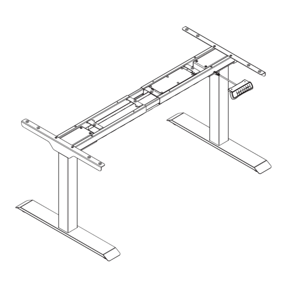
Item No.: UN-SS-Straight-Q2
Technical data
Column Stage
3
Max. Weight Capacity
275lbs/125KG
Height Range
22.8"- 48.4"/580-1230mm (without tabletop)
Width Range
43.3"- 74.8"/1100-1900mm
Component list
No.
Part
Qty No.
Part
Qty
1
2
2
2
Feet
Lifting Column
Qty No.
Qty
No.
Part
Part
3
1
4
1
Supporting Beam
Cable Management Tray
(Control Box included)
Qty No.
Qty
No.
Part
Part
1
5
6
2
Hand Switch
Side Bracket
(Option)
Qty
Qty
No.
Part
No.
Part
7
1
8
1
Power Plug
Installation guide
Accessory list
Attention: The drawings below are for guidance only and they may differ
slightly from the product and fittings received. Please contact our customer
service department should you have any queries.
No.
Image
Spec
A
M6
B
M6
C
M6
D
M6
E
St4. 2
Allen Key
F
4x4mm
Or
The hand drill or Phillips screwdriver
prepared by the customers.
Self adhesive bag list
3
5
2
1
STEP 1
Install the Side Brackets
A
x4
F
4x4
Qty
4
4
5
8
12
16
1
STEP 2
Install the Lifting Columns
D
x8
F
4x4
6
STEP 3
Install the Feet
C
x8
F
4x4
7
4
Attach the side brackets(5) to the ends of the supporting beam (4) using
screws(A) as show with the Allen Key(F).
A
2
F
D
4
Insert the lifting columns (2) into the ends of the supporting beam(4).
Fix the lifting columns using screws(D) with the Allen Key(F).
F
C
2
Place the feet(1) on the bottom of the lifting column(2).
Fix the feet using screws(C) with Allen Key(F).
F
A
5
1
1
Advertisement

Related Manuals for Skutchi UN-SS-Straight-Q2


Summary of Contents for Skutchi UN-SS-Straight-Q2
- Page 1 STEP 1 Install the Side Brackets Item No.: UN-SS-Straight-Q2 Installation guide Accessory list Attention: The drawings below are for guidance only and they may differ slightly from the product and fittings received. Please contact our customer service department should you have any queries.
- Page 2 STEP 4 Install the Tabletop and Hook Loosen Method 2 Install the cable management tray as Method 1, Step 6. Adjust Option 2 Option 1 Hook can be installed in appropriate position according to customer’s actual requirements When the supporting beam stretches over 1720 mm, Tighten the cable management tray needs to be mounted on the middle of the supporting beam.
- Page 3 Attention Common fault treatment The following tips will help you detected and eliminate the common fault and error.If the fault you met is not listed below, please contact with your 1. Power supply: AC100V- 240V,50/60Hz supplier. Only themanufacturer and professionals are capable for investigating 2.
Need help?
Do you have a question about the UN-SS-Straight-Q2 and is the answer not in the manual?
Questions and answers