Advertisement
Quick Links
INSTRUCTION MANUAL
BEFORE USE ....
Thank you for choosing us. Before use, please check con-
tents of the package you received as outlined below.
If you have any problems or questions with the product,
please contact our sales office or representatives.
■ PACKAGE INCLUDES:
AC alarm (body + base socket) ...........................................(1)
■ MODEL NO.
Confirm Model No. marking on the product to be exactly
what you ordered.
■ INSTRUCTION MANUAL
This manual describes necessary points of caution when
you use this product, including installation, connection and
basic maintenance procedures.
POINTS OF CAUTION
■ POWER INPUT RATING & OPERATIONAL RANGE
• Locate the power input rating marked on the product and
confirm its operational range as indicated below:
AC power: Rating ±10%, 50/60 ±2 Hz, approx. 2VA
DC power: Rating ±10%, approx. 2W
or 85 – 150V, approx. 2W for 110V rating
■ GENERAL PRECAUTIONS
• Before you remove the unit from its base socket or mount
it, turn off the power supply and input signal for safety.
■ ENVIRONMENT
• Indoor use.
• When heavy dust or metal particles are present in the
air, install the unit inside proper housing with sufficient
ventilation.
• Do not install the unit where it is subjected to continuous
vibration. Do not subject the unit to physical impact.
• Environmental temperature must be within -5 to +60°C
(23 to 140°F) with relative humidity within 30 to 90% RH
in order to ensure adequate life span and operation.
■ WIRING
• Do not install cables close to noise sources (relay drive
cable, high frequency line, etc.).
• Do not bind these cables together with those in which
noises are present. Do not install them in the same duct.
■ AND ....
• The unit is designed to function as soon as power is sup-
plied, however, a warm up for 10 minutes is required for
satisfying complete performance described in the data
sheet.
MG CO., LTD. www.mgco.jp
5-2-55 Minamitsumori, Nishinari-ku, Osaka 557-0063 JAPAN
AC ALARM
MODEL
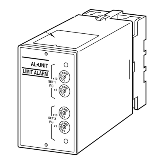
COMPONENT IDENTIFICATION
Body
Specifications
AL •U NI T
LIM IT AL AR
M
x10
SET 1
(%)
x1
x10
SET 2
(%)
x1
■ FRONT PANEL CONFIGURATION
No.1 LED
No.1 Setpoint Rotary SW (x10%)
No.1 Setpoint Rotary SW (x1%)
No.2 Setpoint Rotary SW (x10%)
No.2 Setpoint Rotary SW (x1%)
No.2 LED
• No. 1 LED
Turns on when No. 1 alarm is tripped and coil is energized.
• No. 1 Setpoint Rotary SW (×10%)
Used for setting the tens place of No. 1 alarm setpoint in %.
• No. 1 Setpoint Rotary SW (×1%)
Used for setting the ones place of No. 1 alarm setpoint in %.
• No. 2 Setpoint Rotary SW (×10%)
Used for setting the tens place of No. 2 alarm setpoint in %.
• No. 2 Setpoint Rotary SW (×1%)
Used for setting the ones place of No. 2 alarm setpoint in %.
• No. 2 LED
Turns on when No. 2 alarm is tripped and coil is energized.
ALAC
Base Socket
EM-2736 Rev.9 P. 1 / 3
Advertisement

Related Manuals for MG ALAC


Summary of Contents for MG ALAC
- Page 1 • The unit is designed to function as soon as power is sup- plied, however, a warm up for 10 minutes is required for satisfying complete performance described in the data sheet. EM-2736 Rev.9 P. 1 / 3 MG CO., LTD. www.mgco.jp 5-2-55 Minamitsumori, Nishinari-ku, Osaka 557-0063 JAPAN...
- Page 2 ■ CONNECTION DIAGRAM INPUT SETPOINT 1 OUTPUT SETPOINT 2 OUTPUT U(+) POWER V(–) *Relay status for output codes “1” & “4”, at power OFF. EM-2736 Rev.9 P. 2 / 3 MG CO., LTD. www.mgco.jp 5-2-55 Minamitsumori, Nishinari-ku, Osaka 557-0063 JAPAN...
- Page 3 Output Code: 1 & 4: Terminals 1 – 2, 9 – 10 turn ON • Output Code: 2 & 3: Terminals 1 – 3, 9 – 11 turn ON EM-2736 Rev.9 P. 3 / 3 MG CO., LTD. www.mgco.jp 5-2-55 Minamitsumori, Nishinari-ku, Osaka 557-0063 JAPAN...
Need help?
Do you have a question about the ALAC and is the answer not in the manual?
Questions and answers