Table of Contents
Advertisement
Quick Links
INSTRUCTION MANUAL
(thumbwheel switch adjustment)
BEFORE USE ....
Thank you for choosing us. Before use, please check con-
tents of the package you received as outlined below.
If you have any problems or questions with the product,
please contact our sales office or representatives.
■ PACKAGE INCLUDES:
DC alarm (body + base socket + input resistor) ................(1)
Input resistor is provided only with current input type.
■ MODEL NO.
Confirm Model No. marking on the product to be exactly
what you ordered.
■ INSTRUCTION MANUAL
This manual describes necessary points of caution when
you use this product, including installation, connection and
basic maintenance procedures.
POINTS OF CAUTION
■ CONFORMITY WITH EU LVD DIRECTIVE
• This equipment is suitable for Pollution Degree 2, Meas-
urement Category II (output, transient voltage 2500V)
and Installation Category II (transient voltage 2500V).
Basic insulation (signal input to output to power input:
300V) is maintained. Prior to installation, check that the
insulation class of this unit satisfies the system require-
ments.
• Altitude up to 2000 meters.
• The equipment must be mounted inside a panel.
• The equipment must be installed such that appropriate
clearance and creepage distances are maintained to con-
form to CE requirements. Failure to observe these re-
quirements may invalidate the CE conformance.
■ CONFORMITY WITH EU EMC DIRECTIVE
• The actual installation environments such as panel
configurations, connected devices, connected wires, may
affect the protection level of this unit when it is inte-
grated in a panel system. The user may have to review
the CE requirements in regard to the whole system and
employ additional protective measures* to ensure the
CE conformity.
* For example, installation of noise filters and clamp fil-
ters for the power source, input and output connected
to the unit, etc.
• Install lightning surge protectors for those wires connect-
ed to remote locations.
■ POWER INPUT RATING & OPERATIONAL RANGE
• Locate the power input rating marked on the product and
confirm its operational range as indicated below:
100 – 120V AC rating: 90 – 132V, 47 – 66 Hz, approx. 3VA
200 – 240V AC rating: 180 – 264V, 47 – 66 Hz, approx. 3VA
■ GENERAL PRECAUTIONS
• Before you remove the unit from its base socket or mount
it, turn off the power supply and input signal for safety.
MG CO., LTD. www.mgco.jp
5-2-55 Minamitsumori, Nishinari-ku, Osaka 557-0063 JAPAN
DC ALARM
MODEL
■ ENVIRONMENT
• Indoor use.
• When heavy dust or metal particles are present in the
air, install the unit inside proper housing with sufficient
ventilation.
• Do not install the unit where it is subjected to continuous
vibration. Do not subject the unit to physical impact.
• Environmental temperature must be within -5 to +60°C
(23 to 140°F) with relative humidity within 30 to 90% RH
in order to ensure adequate life span and operation.
■ WIRING
• Do not install cables close to noise sources (relay drive
cable, high frequency line, etc.).
• Do not bind these cables together with those in which
noises are present. Do not install them in the same duct.
■ AND ....
• The unit is designed to function as soon as power is sup-
plied, however, a warm up for 10 minutes is required for
satisfying complete performance described in the data
sheet.
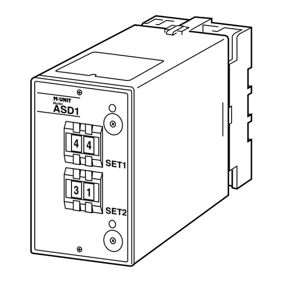
COMPONENT IDENTIFICATION
Body
Specifications
Mod el
A S D 1
4 4
SE T1
3
1
SE T2
■ FRONT PANEL CONFIGURATION
9 9
9 9
ASD1
Base Socket
Input Resistor
•Output 1
Monitor LED
Deadband & Latching Control
Setpoint Adj.
•Output 2
Setpoint Adj.
Monitor LED
Deadband & Latching Control
EM-1610 Rev.6 P. 1 / 3
Advertisement
Table of Contents

Related Manuals for MG ASD1


Summary of Contents for MG ASD1
- Page 1 ■ GENERAL PRECAUTIONS • Before you remove the unit from its base socket or mount it, turn off the power supply and input signal for safety. EM-1610 Rev.6 P. 1 / 3 MG CO., LTD. www.mgco.jp 5-2-55 Minamitsumori, Nishinari-ku, Osaka 557-0063 JAPAN...
- Page 2 INPUT – OUTPUT 1 N.O. N.C. OUTPUT 2 N.O. POWER Input shunt resistor attached *Input shunt resistor attached for current input. for current input. EM-1610 Rev.6 P. 2 / 3 MG CO., LTD. www.mgco.jp 5-2-55 Minamitsumori, Nishinari-ku, Osaka 557-0063 JAPAN...
- Page 3 Output 2 (9-11)ON Input Output 2 Output 1 Setpoint Setpoint Trip Operation in Power Failure : Terminals 1 – 3, 9 – 11 turn ON. EM-1610 Rev.6 P. 3 / 3 MG CO., LTD. www.mgco.jp 5-2-55 Minamitsumori, Nishinari-ku, Osaka 557-0063 JAPAN...
Need help?
Do you have a question about the ASD1 and is the answer not in the manual?
Questions and answers