Table of Contents
Advertisement
Quick Links
INSTRUCTION MANUAL
BEFORE USE ....
Thank you for choosing us. Before use, please check con-
tents of the package you received as outlined below.
If you have any problems or questions with the product,
please contact our sales office or representatives.
■ PACKAGE INCLUDES:
Signal conditioner ...............................................................(1)
■ MODEL NO.
Confirm Model No. marking on the product to be exactly
what you ordered.
■ INSTRUCTION MANUAL
This manual describes necessary points of caution when
you use this product, including installation, connection and
basic maintenance procedures.
POINTS OF CAUTION
■ POWER INPUT RATING & OPERATIONAL RANGE
• Locate the power input rating marked on the product and
confirm its operational range as indicated below:
24V DC rating: 24V ±10%, approx. 80mA
■ GENERAL PRECAUTIONS
• Before you remove the unit or mount it, turn off the power
supply and input signal for safety.
■ ENVIRONMENT
• Indoor use.
• When heavy dust or metal particles are present in the
air, install the unit inside proper housing with sufficient
ventilation.
• Do not install the unit where it is subjected to continuous
vibration. Do not subject the unit to physical impact.
• Environmental temperature must be within -5 to +55°C
(23 to 131°F) with relative humidity within 30 to 90% RH
in order to ensure adequate life span and operation.
■ WIRING
• Do not install cables close to noise sources (relay drive
cable, high frequency line, etc.).
• Do not bind these cables together with those in which
noises are present. Do not install them in the same duct.
■ AND ....
• The unit is designed to function as soon as power is sup-
plied, however, a warm up for 10 minutes is required for
satisfying complete performance described in the data
sheet.
MG CO., LTD. www.mgco.jp
5-2-55 Minamitsumori, Nishinari-ku, Osaka 557-0063 JAPAN
DC ALARM
MODEL
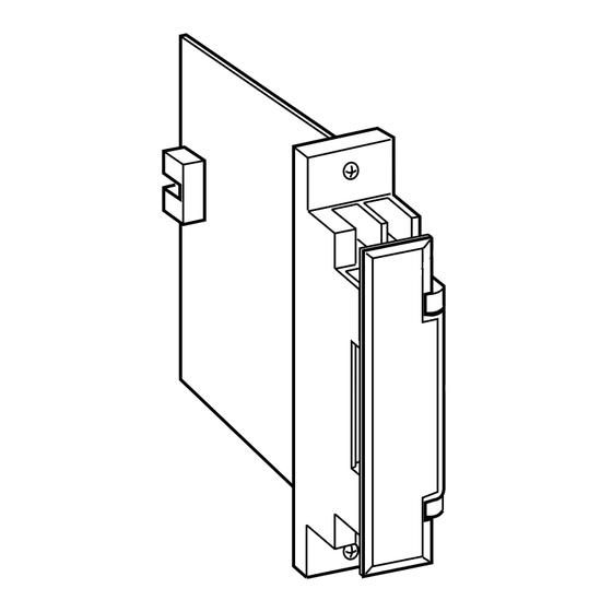
COMPONENT IDENTIFICATION
■ FRONT VIEW (with cover open)
• SINGLE ALARM
7
Indicator
5
Setpoint Adj.
1
3
• DUAL ALARM
7
Hi Alarm Indicator
5
High Setpoint Adj.
Low Setpoint Adj.
Lo Alarm Indicator
1
3
• Single Alarm Trip
Simulate an input for the desired setpoint, then turn the
top mounted screw driver adjustment slowly clockwise until
the output relay trips.
• Hi/Lo Alarm Trip
Lo Setpoint: Simulate an input for the desired setpoint,
then turn the screw driver adjustment slowly counterclock-
wise until the output relay trips.
Hi Setpoint: Simulate an input for the desired setpoint, then
turn the screw driver adjustment slowly clockwise until the
output relay trips.
18AS2
Body
Specifications
Front Cover
(Connection diagram
behind)
8
6
2
4
8
6
2
4
EM-1769 Rev.1 P. 1 / 3
Advertisement
Table of Contents

Related Manuals for MG 18AS2


Summary of Contents for MG 18AS2
- Page 1 Hi Setpoint: Simulate an input for the desired setpoint, then turn the screw driver adjustment slowly clockwise until the output relay trips. EM-1769 Rev.1 P. 1 / 3 MG CO., LTD. www.mgco.jp 5-2-55 Minamitsumori, Nishinari-ku, Osaka 557-0063 JAPAN...
- Page 2 INPUT LO OUTPUT – – OUTPUT HI OUTPUT HI / LO OUTPUT POWER POWER *Relay status is determined by output codes. ■ TERMINAL ASSIGNMENTS EM-1769 Rev.1 P. 2 / 3 MG CO., LTD. www.mgco.jp 5-2-55 Minamitsumori, Nishinari-ku, Osaka 557-0063 JAPAN...
- Page 3 5 – 6 7 – 8 CODE 5 – 6 7 – 8 5 – 6 7 – 8 Shades indicates that the relay is energized. EM-1769 Rev.1 P. 3 / 3 MG CO., LTD. www.mgco.jp 5-2-55 Minamitsumori, Nishinari-ku, Osaka 557-0063 JAPAN...
Need help?
Do you have a question about the 18AS2 and is the answer not in the manual?
Questions and answers