Table of Contents
Advertisement
Quick Links
671047
This document contains confidential information that is the property of Alemite LLC
and is not to be copied, used, or disclosed to others without express written permission
Service Guide
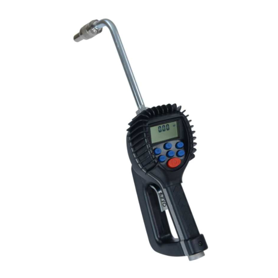
Electronic Preset Meter
3580 Series RF 2.4 GHz
Alemite LLC
167 Rowand Drive, Johnson City, Tennessee 37601
www.alemite.com
Copyright
2013 by Alemite LLC
©
3580-A
3580-B
SER 3580
Revision (07-14)
Advertisement
Table of Contents

Subscribe to Our Youtube Channel
Related Manuals for Alemite 3580 Series


Summary of Contents for Alemite 3580 Series
- Page 1 167 Rowand Drive, Johnson City, Tennessee 37601 www.alemite.com Copyright 2013 by Alemite LLC © 671047 This document contains confidential information that is the property of Alemite LLC SER 3580 Revision (07-14) and is not to be copied, used, or disclosed to others without express written permission...
-
Page 2: Table Of Contents
Network Program....16 Power Level Display....16 Revision (7-14) Alemite, LLC... -
Page 3: Safety
• Comply with all local, state, and federal fire, electrical and safety regulations. • Use of this product in a manner other than specified in this manual may result in impaired operation or damage to equipment. Revision (7-14) Alemite, LLC... -
Page 4: Electronic Preset Meter Description
However, no responsibility is assumed compliance, operations at closer distances than this are for inaccuracies, nor does Alemite LLC. assume any liability not recommended. arising out of the application and use of the equipment described. -
Page 5: Operation
2 Displays unit of measure 3 Arrows flash when RF communication is in progress with the keypad 4 Preset Batch quantity 5 History Icon 6 AUTO is an indicator of being in EPM mode 7 Low Battery Icon Revision (7-14) Alemite, LLC... -
Page 6: Meter Installation
If the system has multiple dispense postions, begin at the position farthest from the pump and move towards the pump. CAUtIon f this installation is new or if the fluid in the lines is contaminated, flush the system before installing the meter(s). Revision (7-14) Alemite, LLC... -
Page 7: Apply Meter To Hose
2. Thread the nozzle onto the meter. Screw it in tightly with an open ended, adjustable wrench. 3. Open all dispense position shut-off valves. Start the pump to pressurize the system. 4. Before use, to ensure accuracy, purge all air from the fluid lines and dispense valve(s). model. Revision (7-14) Alemite, LLC... -
Page 8: Meter Operation, Rf Mode
5. Press the Reset button when finished to complete the dispense order. a. The total quantity dispensed is transmitted to the RF system. b. The meter returns to the locked position. c. The meter is now ready to receive another dispense order from the RF system. Revision (7-14) Alemite, LLC... -
Page 9: History Icon
To input a valid Scale Factor for the meter follow the instructions in the Change Factory Settings section of this manual. All other Are for factory purposes only. error Codes To clear the meter, press Reset. Revision (7-14) Alemite, LLC... -
Page 10: Meter Operation, Epm Mode
For RF and BATCH programming, the meter automatically shuts off if the trigger is pulled and the meter does not sense any flow. Also, in case of an emergency or to interrupt a batch, the meter is equipped with an Emergency Override. (Refer to the "Emergency Override" on page 11 section of this manual.) Revision (7-14) Alemite, LLC... -
Page 11: Return To Rf Mode
In case of an emergency or to interrupt a batch, the meter is equipped with an Emergency Override. 1. Press the red O button to activate the Emergency Override. The override closes the valve, immediately stopping fluid flow. 2. Batching can continue after an Emergency Override by pulling up on the trigger. Revision (7-14) Alemite, LLC... -
Page 12: Calculating The Scale Factor
4. To calculate a new factor: 1.0123 (existing Scale Factor) x 1.05 (error factor) = 1.0629 (new Scale Factor). 5. Enter that number as described in the Change Scale Factor section of this manual. note: Use the scale Factor showing on the display, not one written on the trigger. Revision (7-14) Alemite, LLC... - Page 13 Figure 6: Chart of Approximate Scale Factors for Fluids of Different Viscosities Fluid Viscosity scale Factor Water/Anti-Freeze 1.044 Anti-Freeze 1.007 Brake Fluid 1.004 1.002 1.000 80W-90 0.999 140W 1800 0.993 Table 2: Samples of Fluids, Viscosities and Scale Factors Revision (7-14) Alemite, LLC...
-
Page 14: Changing Factory Settings
4. If no Scale Factor changes are necessary, press and hold the totAL and AUto buttons until the display flashes three times, then goes blank OR Press the Reset button to advance to the EPM Manual Mode Enable screen. Revision (7-14) Alemite, LLC... -
Page 15: Changing The Scale Factor
When the AUTO icon is turned off the key sequence is disabled and the meter cannot be put in EPM mode. Press the Reset button to advance to the Network Program screen. Revision (7-14) Alemite, LLC... -
Page 16: Network Program
To save your changes and exit the programming mode. 1. Press and hold down the totAL and AUto buttons at the same time. The display will flash 3 times and go blank. 2. Press the Reset button to turn on the display. Revision (7-14) Alemite, LLC... -
Page 17: Dimensions
5-Digit LCD Display, 10 mm high x 5 mm wide Quarts (liters), pints, gallons Inlet and outlet Connections 1/2" NPT (1/2" BSPP) * Tested with DTE-25 motor oil at ambient temperature. Minimum/maximum flow range will vary with fluid viscosity. Revision (7-14) Alemite, LLC... -
Page 18: Parts List
SER 3580 Electronic Preset Meter Item # Description Part number Battery holder assembly 393810-6 Bottom case with screws and radio 393810-1 Solenoid 393810-2 Revision (7-14) Alemite, LLC... - Page 19 SER 3580 Electronic Preset Meter Item # Description Part number Rubber boot 393810-7 Display assembly 393810-8 RF register assembly 393810-5 Not Shown Swivel, NPT AFLAS 393810-9 Revision (7-14) Alemite, LLC...
- Page 20 SER 3580 Electronic Preset Meter Item # Description Part number Valve assembly – AFLAS 393810-3 LCP gear set with AFLAS o-ring 393810-4 Trigger assembly 393810-10 Revision (7-14) Alemite, LLC...
-
Page 21: Troubleshooting
Pump pressure is low Turn up the pump pressure Foreign material is jamming Contact your local distributor for repair meter Meter inaccurate Scale factor not correct for Enter program mode, check and reset program factor fluid Revision (7-14) Alemite, LLC... -
Page 22: Maintenance
Changes since Last Printing Replace meter photo and added Meter Table Loctite and 243 are trademarks of Henkel Corporation in the U.S. and elsewhere. ® denotes a trademark registered in the U.S. Patent and Trademark Office Revision (7-14) Alemite, LLC... - Page 23 This page is intentionally left blank...
- Page 24 SER 3580 Electronic Preset Meter Revision (7-14) Alemite, LLC...
Need help?
Do you have a question about the 3580 Series and is the answer not in the manual?
Questions and answers