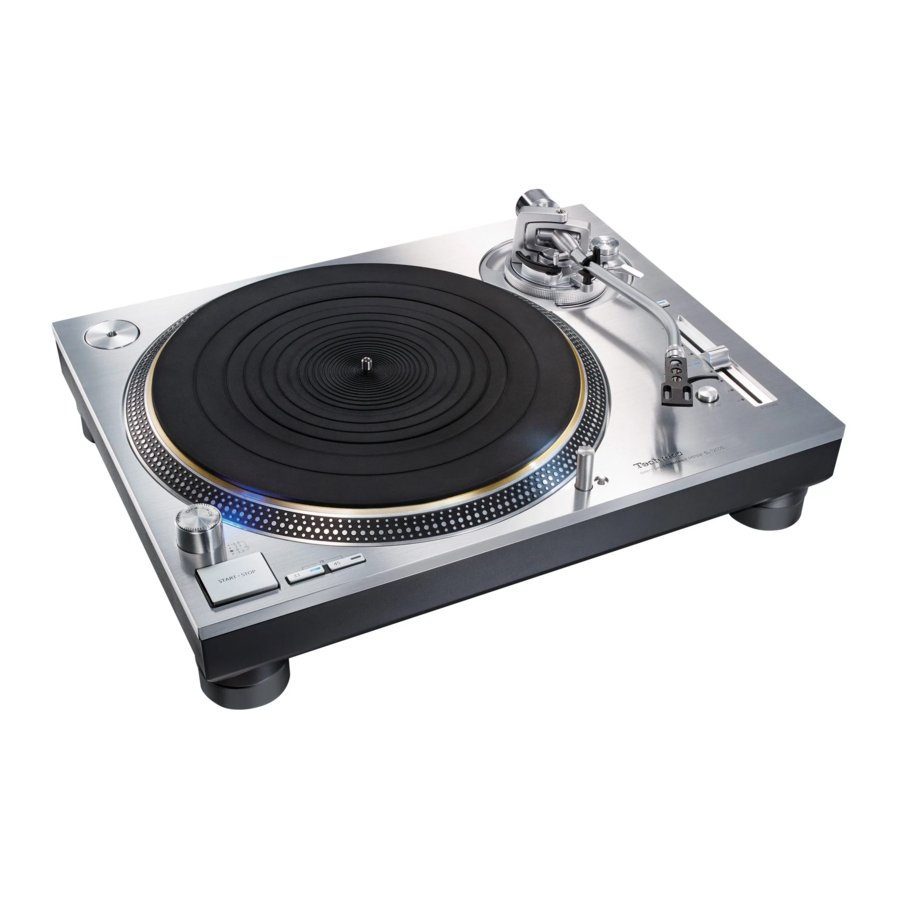
Technics SL-1200G / SL-1210G - Direct Drive Turntable System Manual
- Operating instructions manual (248 pages) ,
- Owner's manual (52 pages) ,
- Owner's manual (51 pages)
Advertisement
Features
The coreless direct drive eliminates cogging and achieves smooth rotation
- The twin-rotor construction reduces minute vibration during rotation while maintaining high torque.
- The high-precision motor control technology switches the drive mode depending on the operational status of the motor.
This technology combines high torque with high stability.
The tone arm with high-precision bearings achieves high initialmotion sensitivity
- The tone arm pipe employs magnesium which provides high rigidity.
- The use of traditional Technics gimbal suspension construction and high-precision bearings attains high initial-motion sensitivity.
Three-layered turntable that delivers smooth rotational stability
- The turntable has a three-layered construction with a rigidly combined brass and aluminium diecast platter, and a rubber covering its rear surface to eliminate unnecessary resonance. With this construction, high rigidity and vibration damping are achieved.
- The use of a heavyweight-class turntable that generates a large inertial mass.
It delivers smooth rotational stability.
Four-layered cabinet construction and insulators based on thorough anti-vibration design
- The top panel of immaculate aluminum has been added to the three-layered construction of aluminum diecast, BMC, and heavyweightclass rubber. This four-layered construction combines high rigidity with a high quality finish and feel.
- The insulators employ special silicon rubber to ensure high vibration damping and longterm reliability. They completely dampen external vibration and suppress howling noise.
High-quality terminals
- The use of brass-milled and gold-plated terminals prevents degradation in sound quality.
- Inside the case, the metal shielding construction is used to diminish the effects of external noise.
Highly accurate turntable speed maintained with the pitch control
- The digital control method is adopted to achieve constant pitch control.
- The pitch variable range select button (×2) is provided. The pitch control with the range up to ±16% is possible.
Accessories
In order to prevent damage during shipping some of the equipment has been disassembled. Please check and identify the supplied accessories.
 Turntable (1 pc.) (TTV0143) |  Turntable mat (1 pc.) (TEFX5019) |  Dust cover (1 pc.) (TTFA0572) | |
 EP record adaptor (1 pc.) SL-1200G: (TBMX5422) SL-1210G: (TBMX5421) |  Balance weight (1 pc.) SL-1200G: (TYL0541) SL-1210G: (TYL0295) |  Auxiliary weight small (1 pc.) (TPAKK61) | |
 Auxiliary weight big (1 pc.) (TPAKK62) |  Head shell (1 pc.) (TPBAA202) |  Overhang gauge (1 pc.) (RMR2210-W) | |
 Screw set for cartridge (1 set) (RXQ2315)
|  PHONO cable (1 pc.) (K2KYYYY00257) |  PHONO earth lead (1 pc.) (K4EY1YY00160) | |
 AC power supply cord (1 pc.) (K2CG3YY00191) |  Screw set for turntable (1 set) (TTV0142)
| ||
- The model numbers of the accessories are as of July 2021.
They are subject to change without notice. - Dispose of the packaging materials in an appropriate manner.
- Follow the local regulations when disposing of the product.
- Do not use any other AC power supply cord, PHONO cable and PHONO earth lead except the supplied one.
- Keep the cartridge, auxiliary weight, nuts, screws and washers out of reach of children to prevent swallowing.
- Illustrations and figures in this manual are of the silver main body.
Parts Name

Putting the player together
Attaching the cartridge
- Attach a cartridge (store-bought) tentatively.
Follow the cartridge's instructions to correctly attach it to the head shell, and tighten the screws lightly.


| (Lead wire) | (Terminal) | |
| Red | → | R+ (Red) |
| Green | → | R- (Green) |
| White | → | L+ (White) |
| Blue | → | L- (Blue) |
- If the mounting screws are included in the cartridge, use them.
- When playing SP records, use a cartridge for SP records.
- Use a commercially available mini flat screwdriver (4 mm [5/32 "]).
- Adjust the overhang.
Use the included overhang gauge.- Fit the overhang gauge to the head shell.
![]()
- Move the cartridge to line the stylus tip up with the end of the gauge.
![]()
- The cartridge should be parallel on the shell head when viewed from the top and side (the illustration is the top view).
![]()
- The cartridge should be parallel on the shell head when viewed from the top and side (the illustration is the top view).
- Tighten the screw for cartridge.
![]()
- Be careful not to allow the cartridge to slip out of place.
- Fit the overhang gauge to the head shell.


The overhang can be adjusted optimally.
In order to prevent damage during shipping some of the equipment has been disassembled.
Put the player together in the following order.

Attention
Do not connect the AC power supply cord until set up is complete.
- Do not use an electric screwdriver or impact wrench to tighten screws.
- Note that using a screwdriver not fitting to the screws for mounting the turntable may damage the main unit.
Fitting the unit
- Insert the center spindle in the center hole of the turntable.
Attention
- Be careful when handling the turntable, as it is heavy.
- Wipe off fingerprints or dirt with a soft cloth.
- Slowly lower the turntable while aligning the rotor shaft fix holes (three locations) with the rotor shafts.
- Turn the turntable in both directions to align the holes with the rotor shafts.
Attention
- If the rotor shafts are misaligned, a gap remains between the turntable and main unit and you cannot mount the turntable correctly. Do not force the turntable downward.
![]()

- Attach the washers, belleville springs, and screws for turntable to the rotor shaft fix holes, and tighten the mounting screws securely.
Attention
- When tightening screws, do not allow screw heads to protrude from the top surface of the turntable.
![]()
- Tighten three screws evenly.

To remove the turntable
- Loosen the mounting screws for turntable and remove them.
- Keep the screws, belleville springs, and washers carefully.
- Hold the turntable with both hands and slowly pull it straight up.
Fitting the unit mat
- Lay the turntable mat on the turntable.
Attaching the head shell
- Fit the head shell with the cartridge into the tone arm.
Keep the head shell horizontal and tighten the locking nut.

- Be careful not to touch the stylus tip.

Attaching the balance weight
- Attach the balance weight to the rear of the tone arm.

- Attach the included auxiliary weight to the rear of the tone arm according to the weight of your cartridge.
For adjustable cartridge weight ranges, see "Applicable cartridge weight range".

- Attach the included auxiliary weight to the rear of the tone arm according to the weight of your cartridge.


Note
- The inside of the balance weight is greased.
Connections and installation
- Turn off all units and disconnect the AC power supply cord from the outlet before making any connections.
- Connect the AC power supply cord only after all other connections are completed.
- Be sure to connect the PHONO earth lead. Otherwise mains hum may occur.
- Refer also to the instruction manual of the connected device.
Connecting to an integrated amplifier or component system
- Connect the PHONO cables and PHONO earth lead to the PHONO terminals of the connected equipment.
- You will not have adequate volume or sound quality if the connected amplifier has no PHONO terminals.
- Connect the AC power supply cord.
- Confirm the wattage of the AC outlet on the connected equipment before using it for this unit.
(This unit consumes 14 W.)
- Confirm the wattage of the AC outlet on the connected equipment before using it for this unit.

Note
- Although the AC power switch is in the "OFF" position, the unit is not completely disconnected from the mains. Remove the plug from the main electrical outlet if you will not be using the unit for an extended period of time. Place the unit so the plug can be easily removed.
Installation
Install the unit on a horizontal surface protected from vibrations.
Keep this unit as far as possible from speakers.
Adjusting the height to make the unit horizontal

Raise the main unit to turn the insulators and adjust the height.
- Clockwise (to the right hand) when seen from below: Lowered
- Counter-clockwise (to the left hand) when seen from below: Raised
Attention
- Do not turn the insulators too far.
Doing so may cause them to come off or damage them.
Notes for installation
- Before you move the unit, turn the unit off, pull out the power plug and disconnect all connected devices.
- Ensure the unit is not exposed to direct sunlight, dust, humidity, and heat from a heating appliance.
- This unit may pick up interference from a radio if there is one nearby. Keep the unit as far as possible from a radio.
- Do not install the unit on a heat source.
- Avoid a place with large temperature variations.
- Avoid a place with frequent condensation.
- Avoid an unstable place.
- Do not put an object on the unit.
- Do not install the unit in a confined space such as a book shelf.
- Install the unit at a position well away from walls or other devices to ensure effective heat radiation from the inside of the unit.
- Make sure that the material of the installation location is sufficiently strong to withstand the weight of this unit.
- Note that the unit may be damaged by cigarette smoke or moisture from an ultrasonic humidifier.
Condensation
Think of taking out a cold bottle from a refrigerator. If you leave it in a room for a while, dewdrops will form on the bottle surface. This phenomenon is called "condensation".
- Conditions causing condensation
- Rapid temperature change (caused by moving from a warm place to a cold place or vice versa, rapid cooling or heating, or direct exposure to cooled air)
- High humidity in a room with much steam, etc.
- Rainy season
- Condensation may damage the unit. If it has occurred, turn the unit off and leave it until it adapts to the ambient temperature (approximately 2 to 3 hours).
Fit the dust cover
- Hold the dust cover with both hands and insert it into the dust cover fitting parts (See "Parts Name") on the player.

- To remove the dust cover, keep it open and lift it straight above.

Attention
- Return the tone arm to the arm rest and fix it with the arm clamp before you attach or detach the dust cover.
Adjustment
Horizontal balance
Preparation
- First, remove the dust cover.
- Remove the stylus cover, taking care not to damage the stylus, then release the arm clamp.
- Lower the cue lever.
- Turn the anti-skating control to "0".
- Free the tone arm from the arm rest and adjust horizontal balance by turning the balance weight.
Hold the tone arm and turn the balance weight in the arrow direction to adjust the balance until the arm is approximately horizontal.

- Take care not to allow the stylus tip to touch the turntable or main unit.

Stylus pressure
Preparation
- First, remove the dust cover.
- Return the tone arm to the arm rest and fix it with the arm clamp.
- Turn the stylus pressure control until "0" comes to the center line of the rear of the tone arm.

- Hold the balance weight still while doing this.

Note
- Refer to the user's guide for your stylus for the appropriate stylus pressure.
- Turn the balance weight to adjust to the appropriate stylus pressure for the cartridge.

- The stylus pressure control will turn together with the balance weight.
- Turn until the center line points to the appropriate stylus pressure.

Anti-skating
- Turn the anti-skating control to adjust it to the same value as the stylus pressure control.


Note
- For stylus pressures 3 g and above, adjust anti-skating control to "3".
Tone arm height
Make this adjustment only if the cartridge you are using makes it necessary.
Preparation
- Put a record on the turntable.
- Release the arm lock.

- Adjust the height with the armheight control ring.
Adjust the arm height until the tone arm becomes parallel to a record.- Use the chart below as reference to find the appropriate position mark for the height of your cartridge.

(For supplied head shell)
 | Cartridge height (H) in millimeters | Height control position |
| 17 | 0 | |
| 18 | 1 | |
| 19 | 2 | |
| 20 | 3 | |
| 21 | 4 | |
| 22 | 5 | |
| 23 | 6 |
- Turn the arm-height control ring to align the position mark with the index line.
0 to 6 mm (0" to 15/64") are marked on the arm height control ring.
![]()

When you don't know the cartridge height (H),
Remove the stylus cover, taking care not to damage the stylus, then release the arm clamp. Lower the cue lever, rest the stylus on a record and adjust the height control until the tone arm and record are parallel.

- After arm height adjustment is finished, lock the tone arm by turning the arm lock knob.
Attention
- Be careful not to damage the stylus tip.
- Do not use the product with the arm lock released.
Armlift height
Make an adjustment according to your cartridge if necessary.
Preparation
- Put a record on the turntable.
- Remove the stylus cover, taking care not to damage the stylus, then release the arm clamp.
- Lift the cue lever and move the tone arm over the record.
- Check the armlift height (distance between the stylus tip and record surface).
If adjustment is needed, go to the step 2.

- The armlift height is factory-adjusted to 8 to 13 mm (5/16" to 33/64").
- Return the tone arm to the arm rest, clamp it with the arm clamp and while pressing the armlift down with your finger, turn the screw to adjust the height.

- Turning the screw clockwise lowers the armlift.
- Turning the screw anti-clockwise raises the armlift.


Adjusting the unit startup/brake speed
You can choose manual mode or auto mode.
(Factory setting: Auto mode)

Auto mode
We recommend auto mode that can maximize performance of the product. It adjusts the "startup speed" (described below) automatically.
(The set torque control is not reflected.)
- Move the mode switch to [A] using a tool such as a thin screwdriver.
Manual mode
Allows you to adjust the "startup speed" manually.
- Move the mode switch to [M] using a tool such as a thin screwdriver.
Startup speed
You can adjust the startup speed (the time for the turntable to reach the constant speed) from pressing [START-STOP] and the torque gain at the constant speed.
- Adjust the torque knob using a flat screwdriver.
- H direction: Fast startup
- L direction: Slow startup
Brake speed
You can adjust the brake speed from pressing [START-STOP] until the turntable stops.
(Adjustment is possible in both auto and manual mode.)
- Adjust the brake speed control knob using a flat screwdriver.
- S direction: Slow stop
- F direction: Fast stop
Note
- Use a commercially available mini flat screwdriver (2.4 mm [3/32 "]) to adjust the torque/brake speed control knob.
- Do not turn the knob too far using an excessive force.
Playing records
Preparation
*1 Put a record on the turntable.
*2 Take off the stylus cover and release the arm clamp.

- Turn [ON/OFF] to turn the unit on.
The strobo light comes on. 33-1/3 r/min is automatically selected and the indicator [33] lights.

- Press [START-STOP].
The turntable starts revolving.
![]()
- Press [RESET] to light the pitch control blue LED indicator.
The unit plays at a preset pitch (33-1/3, 45 or 78 r/min) regardless of the [PITCH ADJ] position.
![]()
- Fine adjustment to pitch (See "Pitch control")
- Lift the cue lever and move the tone arm over the record.
![]()
- Lower the cue lever.
The tone arm moves down slowly.
Play starts
![]()


To temporarily stop play
Lift the cue lever.
- The stylus lifts off the record.
- To start play again, lower the cue lever.
When play finishes
- Lift the cue lever, return the tone arm to the arm rest and lower the cue lever.
- Press [START-STOP]. The electronic brake gently stops the turntable.
- Turn [ON/OFF] to turn the unit off.
- Clamp the tone arm with the arm clamp.
- Put the stylus cover back on (to protect the stylus tip).
To light up the stylus
The stylus tip is illuminated during play.

Press the stylus light switch.
- The stylus light (white LED) rises up and illuminates the stylus.
- Press down the stylus light to turn off the light.
Attention
Press the stylus light switch firmly. If the switch is lightly pressed, the light may come on but not rise up.
When playing EP records
- Press the speed select button [45] ([45] lights).
- Fit the EP record adaptor over the center spindle.
When playing SP records
- Press the speed select buttons [33] and [45] at the same time (78 r/min: [33] and [45] light).
When using a record stabilizer
(not included)
- See the instruction manual of the record stabilizer.
- Maximum weight: 1 k g
Pitch control

Fine adjustment to pitch
- Press [RESET] to turn off the blue LED light.
- Press the pitch range select button to select the pitch range.
- [×2] light on: ±16 %
- [×2] light off: ±8% 3
- While the turntable is revolving
Slide [PITCH ADJ].- Pitch can be adjusted between approx. –8% and +8% or approx. –16% and +16% according to your selection.
- The numbers represent approximate percentages for your adjustment.
To reset pitch to the preset value
Press [RESET].
The blue LED indicator lights and the pitch immediately returns to a preset value regardless of the [PITCH ADJ] position.
(33-1/3 , 45 or 78 rpm)
To measure pitch
The four rows of strobe mirrors around the edge of the turntable can assist you in measuring pitch.

- +6.4% change in pitch when stationary
- +3.3% change in pitch when stationary
- Normal turntable speed
(33-1/3 , 45 or 78 r/min) when stationary - -3.3% change in pitch when stationary
Attention
The strobe mirrors are lit by the strobo light (blue LED) synchronizing with the precise frequency of digital control.
Always use the blue LED to measure the pitch.

Maintenance
Care of the parts
Thoroughly clean dust off the stylus and record.
- Take off the head shell with the cartridge and clean the stylus using a soft brush. Brush from the base to the tip.

- Use a record cleaner to keep your records clean.

Wipe the head shell terminals occasionally.
Wipe the head shell terminals with a soft cloth and fit the head shell to the tone arm.
Turn the volume down or turn the amplifier off before fitting or removing the head shell.
Damage to your speakers can occur if the head shell is moved while the volume is turned up.
Cleaning the dust cover
Wipe the dust cover and cabinet with a soft cloth.
When dirt is heavy, wring a wet cloth tightly to wipe the dirt, and then wipe it with a soft cloth.
- Do not use solvents including benzine, thinner, alcohol, kitchen detergent, a chemical wiper, etc. This might cause the exterior case to be deformed or the coating to come off.
- Do not wipe the dust cover while playing a record.
This can cause static electricity. This static can cause the tone arm to be attracted towards the dust cover.
Moving the unit
Repackage the unit in the packaging it came in.
If you no longer have the packaging, do the following:
- Take off the turntable and turntable mat and carefully wrap them.
- Remove the head shell and balance weight from the tone arm and carefully wrap them.
- Clamp the tone arm with the arm clamp and tape it in place.
- Carefully wrap the main unit in a blanket or paper.
Troubleshooting guide
Before requesting service, make the below checks. If you are in doubt about some of the check points, or if the remedies indicated in the chart do not solve the problem, contact your dealer.
No power
- Is the AC power supply cord plugged in?
Plug the cord in firmly. (See "Connections and installation")
There is power but no sound/Sound is weak
- Are connections to the amplifier/receiver's PHONO terminals correct?
Connect the PHONO cables to the amplifier's PHONO terminals. (See "Connections and installation")
Left and right sounds are reversed
- Are the stereo connection cable connections to the amplifier or receiver reversed?
Double check all connections. (See "Connections and installation") - Are connections of the head shell's lead wires to the cartridge terminals correct?
Double check all connections. (See "Putting the player together")
Humming heard during play
- Are there other appliances or their AC power supply cord near the stereo connection cable?
Separate the appliances and their AC power supply cord from this unit. - Is the earth lead connected?
Make sure the earth lead is correctly connected. (See "Connections and installation")
The Strobo light or the blue indicator blinks
Perform the following operations when the strobo light or the blue indicator blinks. The symptom may be improved.
- Turn [ON/OFF] to OFF.
- Pull out the power plug, wait for three seconds, and then insert the plug again.
- Turn [ON/OFF] to ON and press [START-STOP] to rotate the turntable.
- If the strobo light or the blue indicator blinks again, check which one is blinking and contact our service representative.
Updating the firmware
To improve operation or add new functions, the firmware for the unit is updated as needed basis.
Before updating
- From the support website, download the firmware for version upgrade and create a USB memory used for version upgrade.
- See the following website for how to create a USB memory for version upgrade.
www.technics.com/support/firmware/
- Turn [ON/OFF] to OFF and remove the turntable.
- Connect the USB memory for version upgrade to UPDATE terminal of the unit.
![]()
- Turn [ON/OFF] to ON.
![]()
- When update is started, the update lamps light up from left to right.
- Check that all of the four update lamps are lit, and then turn [ON/OFF] to OFF.
- It takes approximately 120 seconds to update the firmware.
- Remove the USB memory.


Attention
- Do not press [START-STOP] when the turntable is removed.
- Use a USB memory with FAT16 or FAT32 format.
- Do not connect any USB device other than the USB memory for version upgrade to the UPDATE terminal of this unit.
- No USB device can be charged from the UPDATE terminal of this unit.
- If after connecting the USB memory and turning [ON/OFF] to ON, the update lamps fail to light up within 15 seconds or they are blinking, see the following website.
www.technics.com/support/firmware/
Specifications
| General | |
| Power supply | AC 120V, 60 Hz |
| Power consumption | 14 W (Power ON) Approx. 0.2 W (Power OFF) |
| Dimensions (W×H×D) | 453 x 173 x 372 mm (17-27/32" × 6- 13/16" × 14-21/32") |
| Mass | Approx. 18.0 k g (39.7lbs) |
| Operating temperature range | 0°C to +40°C |
| Operating humidity range | 35% to 80% RH (no condensation) |
| Turntable section | |
| Type | Direct drive manual turntable |
| Drive method | Direct drive |
| Motor | Brushless DC motor |
| Turntable | Brass and aluminum diecast combined Diameter: 332 mm (13-5/64") Mass: Approx. 3.6 k g (7-15/16 lbs) (including a rubber sheet) |
| Turntable speeds | 33-1/3, 45 and 78 rpm |
| Variable range pitch | ±8% and ±16 % |
| Starting torque | 3.3 k g -cm (2.8 lb-in) |
| Build-up characteristics | 0.7 s. from standstill to 33-1/3 rpm |
| Braking system | Electronic brake |
| Wow and flutter | 0.025% W.R.M.S. (JIS C5521) |
| Rumble | 78 dB (IEC 98A weighted) |
| Tone arm section | |
| Type | Static Balance |
| Effective length | 230 mm (9-1/16") |
| Overhang | 15 mm (19/32") |
| Tracking error angle | Within 2° 32' (at the outer groove of 30 cm (12") record) |
| Within 0° 32' (at the inner groove of 30 cm (12") record) | |
| Offset angle | 22° |
| Arm-height adjustment range | 0 - 6 mm (0" - 15 / 64 ") |
| Stylus pressure adjustment range | 0 - 4 g (direct reading) |
| Head shell weight | Approx. 7.6 g |
| Applicable cartridge weight range | (Without the auxiliary weight) 5.6 to 12.0 g 14.3 to 20.7 g (including the head shell) |
| (With the small auxiliary weight) 10.0 to 16.4 g 18.7 to 25.1 g (including the head shell) | |
| (With the big auxiliary weight) 14.3 to 19.8 g 23.0 to 28.5 g (including the head shell) | |
| Head shell terminal lug | ø 1.2 mm 4-pin terminal lug |
Specifications are subject to change without notice.
IMPORTANT SAFETY INSTRUCTIONS
Read these operating instructions carefully before using the unit. Follow the safety instructions on the unit and the applicable safety instructions listed below.
Keep these operating instructions handy for future reference.
- Read these instructions.
- Keep these instructions.
- Heed all warnings.
- Follow all instructions.
- Do not use this apparatus near water.
- Clean only with dry cloth.
- Do not block any ventilation openings. Install in accordance with the manufacturer's instructions.
- Do not install near any heat sources such as radiators, heat registers, stoves, or other apparatus (including amplifiers) that produce heat.
- Do not defeat the safety purpose of the polarized or grounding-type plug. A polarized plug has two blades with one wider than the other. A grounding type plug has two blades and a third grounding prong. The wide blade or the third prong are provided for your safety. If the provided plug does not fit into your outlet, consult an electrician for replacement of the obsolete outlet.
- Protect the power cord from being walked on or pinched particularly at plugs, convenience receptacles, and the point where they exit from the apparatus.
- Only use attachments/accessories specified by the manufacturer.
- Use only with the cart, stand, tripod, bracket, or table specified by the manufacturer, or sold with the apparatus. When a cart is used, use caution when moving the cart/ apparatus combination to avoid injury from tip-over.
![]()
- Unplug this apparatus during lightning storms or when unused for long periods of time.
- Refer all servicing to qualified service personnel. Servicing is required when the apparatus has been damaged in any way, such as power-supply cord or plug is damaged, liquid has been spilled or objects have fallen into the apparatus, the apparatus has been exposed to rain or moisture, does not operate normally, or has been dropped.


Unit
![burn hazard]()
![shock hazard]()
To reduce the risk of fire, electric shock or product damage,- Do not expose this unit to rain, moisture, dripping or splashing.
- Do not place objects filled with liquids, such as vases, on this unit.
- Use only the recommended accessories.
- Do not remove covers.
- Do not repair this unit by yourself.
Refer servicing to qualified service personnel.

AC power supply cord
- The power plug is the disconnecting device. Install this unit so that the power plug can be unplugged from the socket outlet immediately.
![shock hazard]() Ensure the earth pin on the power plug is securely connected to prevent electrical shock.
Ensure the earth pin on the power plug is securely connected to prevent electrical shock. - An apparatus with CLASS I construction shall be connected to a power socket outlet with a protective earthing connection.

Unit
- Do not place sources of naked flames, such as lighted candles, on this unit.
Placement
![burn hazard]()
![shock hazard]()
To reduce the risk of fire, electric shock or product damage,- Do not install or place this unit in a bookcase, built-in cabinet or in another confined space.
Ensure this unit is well ventilated. - Do not obstruct this unit's ventilation openings with newspapers, tablecloths, curtains, and similar items.
- Do not install or place this unit in a bookcase, built-in cabinet or in another confined space.
- Keep your speakers at least 10 mm (13/32") away from the system for proper ventilation.
The following mark and symbols are located on bottom of the unit.

RISK OF ELECTRIC SHOCK
DO NOT OPEN
TO REDUCE THE RISK OF ELECTRIC SHOCK, DO NOT REMOVE SCREWS.
NO USER-SERVICEABLE PARTS INSIDE.
REFER SERVICING TO QUALIFIED
 | The lightning flash with arrowhead symbol, within an equilateral triangle, is intended to alert the user to the presence of uninsulated "dangerous voltage" within the product's enclosure that may be of sufficient magnitude to constitute a risk of electric shock to persons. |
 | The exclamation point within an equilateral triangle is intended to alert the user to the presence of important operating and maintenance (servicing) instructions in the literature accompanying the appliance. |
- The illustrations shown may differ from your unit.
If you have any questions, visit:
U.S.A.: http://shop.panasonic.com/support
Canada: www.panasonic.ca/english/support
Register online at http://shop.panasonic.com/support (U.S. customers only)
Documents / Resources
References
Firmware Update | Technics
![shop.panasonic.com]() Panasonic - Official Consumer Product Support
Panasonic - Official Consumer Product Support![www.panasonic.ca]() Panasonic - Official Consumer Product Support
Panasonic - Official Consumer Product Support
Download manual
Here you can download full pdf version of manual, it may contain additional safety instructions, warranty information, FCC rules, etc.
Download Technics SL-1200G / SL-1210G - Direct Drive Turntable System Manual
Advertisement


Need help?
Do you have a question about the SL-1200G and is the answer not in the manual?
Questions and answers