Table of Contents
Advertisement
Quick Links
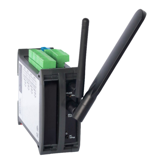
Data visibility for better machine performance
The G3 IoT collates signals from industrial equipment
for processing and publishing to the Cloud. Designed
for monitoring small machines and automation systems,
it enables data visibility for determining machine health
or process efficiency. Industrial grade digital inputs,
relay contacts and analog process input channels
easily link process sensor inputs and standalone legacy
automation such as PLCs, variable frequency drives and
other discrete control systems to IoT cloud services.
Direct wireless interface to field operating data
The G3 IoT converts, conditions and processes analog sig-
nals directly to wireless Wi-Fi (802.11bgn), and the built-in
cloud interface sends data from your machine directly to the
Cloud. A 4G modem (Cat-M1/Cat-1) or Ethernet interface can also be added.
Easily integrates with your existing automation equipment
The G3 IoT natively supports the MQTT communications protocol for Industrial
IoT applications, and Modbus master/slave protocols for directly interfacing
with metering and control automation equipment. The unit's onboard logic
engine allows customization tailored to specific measurement and monitoring
requirements.
Extra cloud interface security and Store and Forward data integrity
The G3 IoT provides peace of mind with Transport Layer Security (TLS 1.2) protocol. In the
event of a network communications failure the G3 IoT Store and Forward function buffers
data locally, forwarding to the cloud server once network communications are reinstated,
securely monitoring and recording with total data integrity.
Base Features
✓
Define Cloud Services connection
MQTT with TLS 1.2
✓
Data record store and forward
✓
record buffer
✓
RTC record data time stamp at origin
Application logic & math functions
✓
PC configuration, USB interface
✓
Wireless Wi-Fi (802.11bgn)
✓
✓
2x 4–20mA inputs (non-isolated)
Edge Processing Interface
4x Digital inputs
✓
3x Relay outputs
✓
1x Auxiliary power output
✓
✓
RS485 Modbus RTU master/slave
Local display (RS485) interface port
✓
AC/DC mains or 11–30V low power
✓
operation
Ǐ
Add-On options available
G3 IoT
- See p3
Advertisement
Table of Contents

Summary of Contents for Define Instruments G3 IoT
- Page 1 Extra cloud interface security and Store and Forward data integrity The G3 IoT provides peace of mind with Transport Layer Security (TLS 1.2) protocol. In the event of a network communications failure the G3 IoT Store and Forward function buffers data locally, forwarding to the cloud server once network communications are reinstated, securely monitoring and recording with total data integrity.
-
Page 2: Table Of Contents
E.1 - Class III Equipment ....62 7.4 - Auxiliary Power Output ..34 7.5 - RS485 Serial Port (Port 2) ..35 G3 IoT Manual | Doc No: 2303-00000-0-1 | Rev: 24V05 | 19 Mar, 2024 © 2024 Define Instruments... -
Page 3: Order Codes
Logs 200 samples. Power Supply (Select) High Voltage (85–265V AC / 120–300V DC) power supply Low Voltage (11–30V DC) power supply G3 IoT Manual | Doc No: 2303-00000-0-1 | Rev: 24V05 | 19 Mar, 2024 © 2024 Define Instruments... - Page 4 *1 OEM customers may be offered additional Analog O option codes constructed from a combination of any one of the following codes: G3 IoT Manual | Doc No: 2303-00000-0-1 | Rev: 24V05 | 19 Mar, 2024 © 2024 Define Instruments...
- Page 5 The Factory Option may be any one of: <Blank>, ‘-VV’, ‘-TV’, ‘-TA’, ‘-TT’, ‘-XX’ Accessories Required Accessories (Sold Separately) USB Bridge Key, required for programming BRIDGE-KEY G3 IoT Manual | Doc No: 2303-00000-0-1 | Rev: 24V05 | 19 Mar, 2024 © 2024 Define Instruments...
-
Page 6: Safety Notices
SAFETY NOTICES For your safety and the prevention of damage to the G3 IoT unit and other equipment connected to it, please read complete instructions prior to installation and operation of the G3 IoT and carefully observe all safety regulations and instructions. Consult this manual carefully in all cases where hazard symbols are marked on the G3 IoT unit. -
Page 7: Symbol Definitions
Veuillez vous référer au manuel d'utilisation. Courant continu. DANGER! Risque de danger Courant continu et alternatif. Veuillez vous référer au manuel d'utilisation. G3 IoT Manual | Doc No: 2303-00000-0-1 | Rev: 24V05 | 19 Mar, 2024 © 2024 Define Instruments... -
Page 8: Cloud Connection
Internet of Things (IoT) capability to an existing ModBus PLC. To get going with your device, visit: defineinstruments.com/go/g3 G3 IoT Manual | Doc No: 2303-00000-0-1 | Rev: 24V05 | 19 Mar, 2024 © 2024 Define Instruments... -
Page 9: Wi-Fi Operating Modes
(See 4.6 for more info.) NOTE: The G3 IoT is capable of running Station Mode and Access Point Mode concurrently. Access Point Mode can only provide local access to device data and settings. It does not allow the device to connect to the internet. -
Page 10: Specifications
Input isolation Not isolated to power supply or digital inputs Debounce counter range 0–100Hz Ǐ Input add-ons available (see p13) Maximum voltage 30V DC G3 IoT Manual | Doc No: 2303-00000-0-1 | Rev: 24V05 | 19 Mar, 2024 © 2024 Define Instruments... - Page 11 Real-Time Clock (RTC) RTC time base UTC. Local time in device with automatic daylight savings adjustment Ǐ 16GB SD add-on available (see p13) G3 IoT Manual | Doc No: 2303-00000-0-1 | Rev: 24V05 | 19 Mar, 2024 © 2024 Define Instruments...
- Page 12 Required mounting height with antenna(s) Wi-Fi antenna only: 6.69" (170mm) Both antennas: 7.28" (185mm) Ǐ Ex Approved available as an optional extra (see p13) G3 IoT Manual | Doc No: 2303-00000-0-1 | Rev: 24V05 | 19 Mar, 2024 © 2024 Define Instruments...
-
Page 13: Expansion Options
SD Card 16GB additional storage Internal loop drop 10V max Resolution 15 bits, 16000 steps Linearity & repeatability 0.1% FSO max Accuracy 0.1% FSO max G3 IoT Manual | Doc No: 2303-00000-0-1 | Rev: 24V05 | 19 Mar, 2024 © 2024 Define Instruments... - Page 14 Isolation test voltage 1500V AC, 2 seconds G3 IoT Manual | Doc No: 2303-00000-0-1 | Rev: 24V05 | 19 Mar, 2024 © 2024 Define Instruments...
- Page 15 Format 8 bit, no parity, 1 stop bit Max current per solid state output 0.3A DC, protected by 1.1A PTC resettable fuse. Inbuilt flyback diode G3 IoT Manual | Doc No: 2303-00000-0-1 | Rev: 24V05 | 19 Mar, 2024 © 2024 Define Instruments...
-
Page 16: Dimensions & Front Panel
DIMENSIONS & FRONT PANEL 4.1 - Dimensions (Base Unit) 4.72" (120mm) 0.91" (23mm) G3 IoT Manual | Doc No: 2303-00000-0-1 | Rev: 24V05 | 19 Mar, 2024 © 2024 Define Instruments... -
Page 17: Dimensions (Expanded Units)
–AO2 –SBS1 –AO8 –UI2–AO2 –UI4–AO4 –UI4–PI8 –PI16 +2 EXPANDERS +2 EXPANDERS +2 EXPANDERS –UI12 –DO32–DI32 –UI16 –SBS2 –UI8–AO8 –SBS1–DO16–DI16 –UI8–PI16 –UI12–PI8 –PI16–AO8 G3 IoT Manual | Doc No: 2303-00000-0-1 | Rev: 24V05 | 19 Mar, 2024 © 2024 Define Instruments... -
Page 18: Front Panel
See 4.4 for models where the Data Logging Add On has been purchased. See PC Programming Port See 6.2 4.8 for more information. G3 IoT Manual | Doc No: 2303-00000-0-1 | Rev: 24V05 | 19 Mar, 2024 © 2024 Define Instruments... - Page 19 See 7.13 Sensor Port 3 Sensor Port 7 See 7.13 See 7.13 Sensor Port 4 Sensor Port 8 See 7.13 See 7.13 G3 IoT Manual | Doc No: 2303-00000-0-1 | Rev: 24V05 | 19 Mar, 2024 © 2024 Define Instruments...
-
Page 20: Power Led
It may be doing a firmware update during this time. Do not turn it off for several minutes to allow it to finish the update. G3 IoT Manual | Doc No: 2303-00000-0-1 | Rev: 24V05 | 19 Mar, 2024 © 2024 Define Instruments... -
Page 21: Mode Led
Firmware Rollback. Attempts to find an older 20–30sec Disconnected version of firmware and revert to it. Fast green flash >30sec Disconnected Normal operation None. Normal boot. G3 IoT Manual | Doc No: 2303-00000-0-1 | Rev: 24V05 | 19 Mar, 2024 © 2024 Define Instruments... -
Page 22: Module Status Led
(such as long term store and forward). G3 IoT Manual | Doc No: 2303-00000-0-1 | Rev: 24V05 | 19 Mar, 2024 © 2024 Define Instruments... -
Page 23: Installation
N.B. Exterior mounting is only suitable for enclosure Fig 2 indoor/covered outdoor environments where antenna is protected from rain or wet conditions. G3 IoT Manual | Doc No: 2303-00000-0-1 | Rev: 24V05 | 19 Mar, 2024 © 2024 Define Instruments... - Page 24 DIN rail. IMPORTANT! The supplied Wi-Fi and/or cellular antennas are not suitable for outdoor or wet environments. G3 IoT Manual | Doc No: 2303-00000-0-1 | Rev: 24V05 | 19 Mar, 2024 © 2024 Define Instruments...
-
Page 25: Emc Installation Guidelines
5.3 - EMC Installation Guidelines The G3 IoT has been designed to cope with large EMC disturbances. This has been achieved by continual testing and improvement of filtering and layout techniques. The unit meets CE noise requirements, and even surpasses them in many tests. (For full details and test results, See Appendix A.) -
Page 26: Software Setup
This will launch the WorkBench installer. Depending on your security settings, a 'Security Warning' dialog may appear. If you see the security message, click 'Run'. G3 IoT Manual | Doc No: 2303-00000-0-1 | Rev: 24V05 | 19 Mar, 2024 © 2024 Define Instruments... - Page 27 Click 'Close' to exit. The installer will place an icon on your desktop for easy access to WorkBench. G3 IoT Manual | Doc No: 2303-00000-0-1 | Rev: 24V05 | 19 Mar, 2024 © 2024 Define Instruments...
-
Page 28: Connecting To Your Pc
Do not unplug the Bridge Key or any connecting cables while WorkBench is busy applying changes to the G3 IoT. This may cause loss of settings, or unexpected unit behaviour. -
Page 29: Workbench Interface
Apply Button. Help Panel Wiring diagrams, explanations and helpful tips will automati- cally appear in this panel as you configure the unit. G3 IoT Manual | Doc No: 2303-00000-0-1 | Rev: 24V05 | 19 Mar, 2024 © 2024 Define Instruments... -
Page 30: Workbench Navigation
Configure the relay outputs. These may defineinstruments.com/go/g3 be driven from one or more setpoints, or directly from one of the digital input pins. G3 IoT Manual | Doc No: 2303-00000-0-1 | Rev: 24V05 | 19 Mar, 2024 © 2024 Define Instruments... -
Page 31: Wiring
221°F (105°C). Le calibre du fil doit être choisi dans la plage indiquée dans le tableau de la Section 7.1. N’utilisez uniquement que des conducteurs en cuivre. G3 IoT Manual | Doc No: 2303-00000-0-1 | Rev: 24V05 | 19 Mar, 2024 © 2024 Define Instruments... -
Page 32: Connectors
Sensor Bus See 7.11 Expansion(s) Digital I/O Expansion – Outputs See 7.12 Sensor Bus Expansion – Open Collec- tor Outputs See 7.13 G3 IoT Manual | Doc No: 2303-00000-0-1 | Rev: 24V05 | 19 Mar, 2024 © 2024 Define Instruments... - Page 33 I/O Expansion and the Sensor Bus Expansion. Sensor Bus Exp Legal combinations include: DO8, DI16, DI16–DO16, – Power Supply DI32–DO32, SBS1, SBS2, and DI16–DO16–SBS1 See 7.13 G3 IoT Manual | Doc No: 2303-00000-0-1 | Rev: 24V05 | 19 Mar, 2024 © 2024 Define Instruments...
-
Page 34: Relay Outputs
It is referred to as 'Relay D' in Define WorkBench. Auxiliary Power Output (Relay D) G3 IoT Manual | Doc No: 2303-00000-0-1 | Rev: 24V05 | 19 Mar, 2024 © 2024 Define Instruments... -
Page 35: Rs485 Serial Port (Port 2)
To wire the ISOLATED UNIVERSAL inputs, see Section 8. The G3 IoT has two non-isolated process inputs that are included with the base unit, and can be wired as shown. Analog inputs A and B are fixed function; they will be supplied as 4–20mA inputs for all standard orders, and cannot be reconfigured by the end user. -
Page 36: Rs485 Display Port (Port 3)
Sourcing (active high input). The diagrams in this manual are for Sinking wiring, which is the default configuration. To view Sourcing wiring, please refer to the help information provided in Define WorkBench. G3 IoT Manual | Doc No: 2303-00000-0-1 | Rev: 24V05 | 19 Mar, 2024 © 2024 Define Instruments... -
Page 37: Power Supply
électrique SELV/PELV Classe III* homologuée UL et protégée par un fusible homologué UL de 2A, 250V. * Équipement De Classe III: Voir L'Annexe E.1 G3 IoT Manual | Doc No: 2303-00000-0-1 | Rev: 24V05 | 19 Mar, 2024 © 2024 Define Instruments... -
Page 38: Analog Output Expansion
CH1 and CH2 connectors. 0/4–20mA 0/4–20mA – – CH1 SEC CH2 SEC – – 0/4–20mA 0/4–20mA 4–20mA Input Expansion G3 IoT Manual | Doc No: 2303-00000-0-1 | Rev: 24V05 | 19 Mar, 2024 © 2024 Define Instruments... -
Page 39: Digital I/O Expansion
(right and overleaf), DCOM3 also referring to the labelling on the unit. DO1 to DO8 Load (or 17–24) Load DO9 to DO16 (or 25–32) G3 IoT Manual | Doc No: 2303-00000-0-1 | Rev: 24V05 | 19 Mar, 2024 © 2024 Define Instruments... - Page 40 11-25V CC SELV/PELV Classe III* UL pour alimenter les entrées et sorties numériques. * Équipement De Classe III: Voir L'Annexe E.1 G3 IoT Manual | Doc No: 2303-00000-0-1 | Rev: 24V05 | 19 Mar, 2024 © 2024 Define Instruments...
-
Page 41: Sensor Bus Expansion
Please refer to the wiring diagram (right) to wire the Open Collector Outputs. DC Input 11–25V Open Collector Outputs (1–8 & 9–16) G3 IoT Manual | Doc No: 2303-00000-0-1 | Rev: 24V05 | 19 Mar, 2024 © 2024 Define Instruments... - Page 42 Classe III* UL pour alimenter les sorties à collecteur ouvert du bus de capteur. * Équipement De Classe III: Voir L'Annexe E.1 G3 IoT Manual | Doc No: 2303-00000-0-1 | Rev: 24V05 | 19 Mar, 2024 © 2024 Define Instruments...
-
Page 43: Universal Input Specifications & Wiring
NOTE: This section is for the ISOLATED UNIVERSAL INPUTS which are available as an optional add-on. To wire the NON-ISOLATED PROCESS inputs (included on the base unit), see Section 7.6 (p35). G3 IoT Manual | Doc No: 2303-00000-0-1 | Rev: 24V05 | 19 Mar, 2024 © 2024 Define Instruments... -
Page 44: Current Input
+24V External Supply Supply +24V Supply 2 Wire Loop 3 Wire 4 Wire Powered Transmitter Transmitter Transmitter Current 0/4–20mA 0/4–20mA 4–20mA 0/4–20mA G3 IoT Manual | Doc No: 2303-00000-0-1 | Rev: 24V05 | 19 Mar, 2024 © 2024 Define Instruments... - Page 45 RFI effects, of which magnitude cannot be easily input. predicted. Note 2 All cables must be screened, with screen earthed at one end only. G3 IoT Manual | Doc No: 2303-00000-0-1 | Rev: 24V05 | 19 Mar, 2024 © 2024 Define Instruments...
-
Page 46: Voltage Input
Note 2 All cables must be screened, with screen RFI effects, of which magnitude cannot be easily earthed at one end only. predicted). G3 IoT Manual | Doc No: 2303-00000-0-1 | Rev: 24V05 | 19 Mar, 2024 © 2024 Define Instruments... -
Page 47: Rtd Input
The best practice is to run input cables on a separate earthed cable tray. This will mini- mize RFI effects, of which magnitude cannot be easily predicted. G3 IoT Manual | Doc No: 2303-00000-0-1 | Rev: 24V05 | 19 Mar, 2024 © 2024 Define Instruments... -
Page 48: Thermocouple Input
(especially at low temperatures) the top cover must always be fitted. Avoid draughts (Continued on p49...) G3 IoT Manual | Doc No: 2303-00000-0-1 | Rev: 24V05 | 19 Mar, 2024 © 2024 Define Instruments... -
Page 49: Digital Pulse
Flow rate (uses K-factor) • RPM (uses pulses per revolution) Reed Switch or NPN Open PNP Open Relay Contact Collector Collector Output Output TTL Input G3 IoT Manual | Doc No: 2303-00000-0-1 | Rev: 24V05 | 19 Mar, 2024 © 2024 Define Instruments... -
Page 50: Potentiometer Input
WorkBench software. These ranges must be calibrated using the two point calibration method. Potentiometer G3 IoT Manual | Doc No: 2303-00000-0-1 | Rev: 24V05 | 19 Mar, 2024 © 2024 Define Instruments... -
Page 51: Ac Current Sensor
Ambient drift 50ppm/°C max 0–100.00V or 0–1000.0V This unit accepts input from a high voltage attenuator (HVA-1000, sold separately). Wire the attenuator as shown. G3 IoT Manual | Doc No: 2303-00000-0-1 | Rev: 24V05 | 19 Mar, 2024 © 2024 Define Instruments... -
Page 52: G3 Iot Common Registers
G3 IOT COMMON REGISTERS Below is a list of the commonly used G3 IoT registers, displayed first in Modicon addressing format, and then as a direct address (brackets). For a full register list, please see: defineinstruments.com/g3-registers Function 32 bit signed registers... - Page 53 Aux13 40339 (338) / 40340 (340) 41619 (1618) / 41620 (1619) Aux14 40341 (341) / 40342 (341) 41621 (1620) / 41622 (1621) G3 IoT Manual | Doc No: 2303-00000-0-1 | Rev: 24V05 | 19 Mar, 2024 © 2024 Define Instruments...
- Page 54 8 bit unsigned registers Internal Relays (When Relay Source = Disabled [DCS Control]) Relay Control 48205 (8204) b0-3 = Relay A-D, b4-7 not used G3 IoT Manual | Doc No: 2303-00000-0-1 | Rev: 24V05 | 19 Mar, 2024 © 2024 Define Instruments...
- Page 55 Modicon range. For example, 400,001 is equivalent to 40,001, and 412,345 would be equivalent to 40,001 + 12,344. G3 IoT Manual | Doc No: 2303-00000-0-1 | Rev: 24V05 | 19 Mar, 2024 © 2024 Define Instruments...
-
Page 56: Calibration & Troubleshooting
CALIBRATION & TROUBLESHOOTING 10.1 - Calibration Your G3 IoT has been fully calibrated at the factory, and can be recalibrated in software using Define WorkBench (see Section 6). Scaling to convert the input signal to a desired display value is also done using WorkBench If your unit appears to be behaving incorrectly or inaccurately, refer to troubleshooting before attempting to calibrate it. -
Page 57: Appendix A - Emc Test Results
Meets Criterion A 70% during 25/30 cycles Meets Criterion A Short Interruptions IEC 61000-4-11 0% during 250/300 cycles Meets Criterion A (Note 1) G3 IoT Manual | Doc No: 2303-00000-0-1 | Rev: 24V05 | 19 Mar, 2024 © 2024 Define Instruments... - Page 58 Notes EN61326-1 calls for a Criterion B pass; unit exceeds this by meeting Criterion A. G3 IoT Manual | Doc No: 2303-00000-0-1 | Rev: 24V05 | 19 Mar, 2024 © 2024 Define Instruments...
-
Page 59: Appendix B - Fcc Compliance
(Wi-Fi & Ethernet) The following models (not available in North American markets) have not been tested: G3–IOT–[ –C1 (Wi-Fi & LTE Cat-1) G3 IoT Manual | Doc No: 2303-00000-0-1 | Rev: 24V05 | 19 Mar, 2024 © 2024 Define Instruments... -
Page 60: Appendix C - Ices-003 Compliance
APPENDIX C - ICES-003 COMPLIANCE C.1 - ICES-003 Statement of Compliance The G3 IoT complies with ICES-003, Issue 7, October 15, 2020 as a Class A device when tested in accordance with the methods contained within ANSI C63.4 - 2014. (*1)(*3) -
Page 61: Appendix D - Ex Approved
Transient protection shall be provided that is set at a level not exceeding 140 % of the peak rated voltage value at the supply terminals to the equipment. G3 IoT Manual | Doc No: 2303-00000-0-1 | Rev: 24V05 | 19 Mar, 2024 © 2024 Define Instruments... -
Page 62: Appendix E - Definitions
être disposé autour du câblage des circuits SELV/PELV ou autour du câblage d'autres circuits, sur la base de la norme CEI 60364-4-41. G3 IoT Manual | Doc No: 2303-00000-0-1 | Rev: 24V05 | 19 Mar, 2024 © 2024 Define Instruments... - Page 63 G3 IoT Manual | Doc No: 2303-00000-0-1 | Rev: 24V05 | 19 Mar, 2024 © 2024 Define Instruments...
- Page 64 PO Box 245 Westpark Village, Auckland 0661, New Zealand Ph: +64 (9) 835 1550 Fax: +64 (9) 835 1250 sales@defi neinstruments.com www.defi neinstruments.com G3 IoT Manual | Doc No: 2303-00000-0-1 | Rev: 24V05 | 19 Mar, 2024 © 2024 Define Instruments...
Need help?
Do you have a question about the G3 IoT and is the answer not in the manual?
Questions and answers