
Related Manuals for sDot XB6 Series

Summary of Contents for sDot XB6 Series
- Page 1 EtherNet/IP XB6 Series Slice I/O User Manual Nanjing Solidot Electronic Technology Co., Ltd.
- Page 2 Copyright © 2023 Nanjing Solidot Electronic Technology Co., Ltd. All rights reserved. Without written permission of our company, no organization or individual may extract, copy or transmit part or all of this document. Trademark notice and other Solidot trademarks are all trademarks of Nanjing Solidot Electronic Technology Co., Ltd. All other trademarks or registered trademarks referred to in this document belong to their respective owners.
-
Page 3: Table Of Contents
XB6 Series EtherNet/IP Slice I/O User Manual Table of Contents Table of Contents Product Features ................................. 5 Product Overview ............................5 Product Features ............................5 Application Configuration ..........................6 Naming Rules ................................7 Naming Rules ..............................7 Coupler Naming Rules ..........................7 2.1.1... - Page 4 XB6 Series EtherNet/IP Slice I/O User Manual Table of Contents Wiring ..................................31 Wiring Terminal ............................31 Wiring Instructions and Requirements ....................32 XB6-EI0002 Communication Interface Wiring ..................35 Scenario 1: There Is Only One Set of XB6-EI0002 Modules in the Network ..... 36 6.3.1...
- Page 5 XB6 Series EtherNet/IP Slice I/O User Manual Table of Contents 6.4.25 XB6-A40TM ............................63 6.4.26 XB6-P04A ............................64 6.4.27 XB6-P20D ............................65 6.4.28 XB6-P20DS ............................66 6.4.29 XB6-C01SP ............................67 Common Terminal Expansion Module Wiring Diagram ............68 Operation ..................................69 Modular Application ...........................
-
Page 6: Product Features
Product Features 1.1 Product Overview XB6 series Slice I/O modules adopt the structure of coupler and I/O module combination. The coupler connects the expandable I/O modules to the real-time industrial Ethernet system, and the I/O module communication backplane adopts X-bus, which provides high real-time performance and a wide range of modules, providing users with high-speed data acquisition, optimized system configuration, simplified on-site wiring, and improved system reliability. -
Page 7: Application Configuration
XB6 Series EtherNet/IP Slice I/O User Manual 1 Product Features 1.3 Application Configuration I/O modules Extension I/O modules End cover Coupler module Function modules Function modules power module Application method: Different modules can be combined, including power supply, coupler, digital, analog, relay, temperature, and other modules. -
Page 8: Naming Rules
XB6 Series EtherNet/IP Slice I/O User Manual 2 Naming Rules Naming Rules 2.1 Naming Rules 2.1.1 Coupler Naming Rules Item Value Description Of The Values Bus Type XB: X-bus Product Series 6: Slice I/O EI: EtherNet/IP EC: EtherCAT Bus Protocol... -
Page 9: I/O Module Naming Rules
XB6 Series EtherNet/IP Slice I/O User Manual 2 Naming Rules 2.1.2 I/O Module Naming Rules Item Value Description Of The Values Bus Type XB: X-Bus Product Series 6: Slice A:Analog I/O Module Type Blank:Digital Analog: 0, 4, 8 Number Of Inputs... -
Page 10: List Of Common Modules
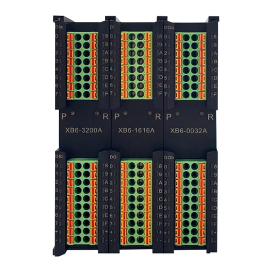
XB6 Series EtherNet/IP Slice I/O User Manual 2 Naming Rules 2.2 List of Common Modules Model Product Description XB6-EI2002ST EtherNet/IP coupler kit (power supply + coupler + cover plate) XB6-P2000 Extension power module XB6-3200A 32-channel digital input module, NPN type... - Page 11 XB6 Series EtherNet/IP Slice I/O User Manual 2 Naming Rules XB6-A04I 4-channel analog output module XB6-0012J 12-channel relay output module XB6-A40TM 4-channel RTD and thermocouple temperature acquisition module XB6-A80TM 8-channel RTD and thermocouple temperature acquisition module XB6-P04A Pulse output module...
-
Page 12: Product Parameters
XB6 Series EtherNet/IP Slice I/O User Manual 3 Product Parameters Product Parameters 3.1 General Parameters General Technical Parameters Power Module 106X61X22.5 Mm Size Coupler Module 106X61X22.5 Mm I/O Modules 106X73X25.7 Mm Power Module 110g Weight Coupler Module 80 g I/O Modules... -
Page 13: Interface Parameter
XB6 Series EtherNet/IP Slice I/O User Manual 3 Product Parameters 3.3 Interface Parameter Ethernet/Ip Interface Parameters Bus Protocol EtherNet/IP Number of I/O Stations Depends on the controller Data Transmission Medium Ethernet CAT5 cable ≤100 m (station to station) Transmission Distance... -
Page 14: Analog Parameter
XB6 Series EtherNet/IP Slice I/O User Manual 3 Product Parameters Channel Indicator Lights Green LED Rated Voltage 24 VDC(18V~30V) Number of Outputs relay output Isolation Method Optocouplers, Relays Rated Load Channel Indicator Lights Green LED light 3.5 Analog Parameter 3.5.1 Technical Parameters... -
Page 15: Voltage I/O Range Selection And Code Value Table
XB6 Series EtherNet/IP Slice I/O User Manual 3 Product Parameters Number of Outputs 4, 8 Output Signal (Voltage Type) 0~+10 V, -10~+10 V (range adjustable) Output Signal (Current Type) 0~20 mA, 4~20 mA (range adjustable) Resolution 16 bit XB6-A04V、XB6-A08V、 ±0.1%... -
Page 16: Current I/O Range Selection And Code Value Table
XB6 Series EtherNet/IP Slice I/O User Manual 3 Product Parameters 3277 3277 2765 2765 6554 6553 5530 5530 9830 9830 8294 8294 13107 13107 11059 11059 16384 16384 13824 13824 19661 19660 16589 16589 22937 22937 19354 19354 26214 26214... - Page 17 XB6 Series EtherNet/IP Slice I/O User Manual 3 Product Parameters Tables3-2 Current Code Values 0 (default) 4-20mA 0-20mA 4-20mA 0-20mA Range Current code value code value code value code value 3277 1382 6554 2765 9830 4147 13107 5530 4096 16384...
-
Page 18: Common Terminal Expansion Module Parameters
XB6 Series EtherNet/IP Slice I/O User Manual 3 Product Parameters 3.6 Common Terminal Expansion Module Parameters Common Terminal Rated Voltage 125 VDC/AC 250V Rated Current Number of Common Terminals 2 sets Copyright © Nanjing Solidot Electronic Technology Co. -
Page 19: Panel
XB6 Series EtherNet/IP Slice I/O User Manual 4 Panel Panel 4.1 Coupler Panel 4.1.1 Coupler Structure Name and function description of each part of the product Number Name Description ① Power interface Push-in terminal blocks ② Guide rail slot Suitable for DIN 35 mm rail fixing ③... -
Page 20: Rotary Switch
XB6 Series EtherNet/IP Slice I/O User Manual 4 Panel 4.1.2 Rotary Switch IP address setting A rotary switch can be used to specify the setting method of the module IP address. Set value (decimal) IP address setting method BOOTP-based settings The factory rotary switch is set to "000", the default state is based on the BOOTP... -
Page 21: Id And Indicators
XB6 Series EtherNet/IP Slice I/O User Manual 4 Panel 4.1.3 ID and Indicators Description of IDs and indicators of the power module Color Status Status description Normal status of working power supply Green Flashing 80% overload. The power supply to real stage load is cut off... -
Page 22: I/O Module Panel
XB6 Series EtherNet/IP Slice I/O User Manual 4 Panel establish a network connection Green No network connection established or abnormal Flashing Connection established with data interaction Yellow No data interaction or exception 4.2 I/O Module Panel Names and functional descriptions of each part of the module... -
Page 23: Installation And Disassembly
XB6 Series EtherNet/IP Slice I/O User Manual 5 Installation and Disassembly Installation and Disassembly 5.1 Installation Guide Module Installation Precautions Ensure that the cabinet is well ventilated. Do not install this unit next to or above equipment that may generate excessive heat. -
Page 24: Installation And Disassembly Steps
XB6 Series EtherNet/IP Slice I/O User Manual 5 Installation and Disassembly Be sure to install the rail mounts 5.2 Installation And Disassembly Steps Module Installation and Removal Module Installation 1. Install the power supply module first on the rail that has been fixed. - Page 25 XB6 Series EtherNet/IP Slice I/O User Manual 5 Installation and Disassembly Press the power module with force until a "click" sound is heard. The module is now installed in place, as shown in the figure②. ② Coupler module installation Steps...
- Page 26 XB6 Series EtherNet/IP Slice I/O User Manual 5 Installation and Disassembly ⑤ End cover installation Steps Install the end cover on the right side of the last module, as shown in the figure⑥, using the same installation method as the coupler module.
- Page 27 XB6 Series EtherNet/IP Slice I/O User Manual 5 Installation and Disassembly Install a guide rail fastener on the right side of the end cover. In this process, first push the guide rail fastener towards the coupler to ensure that the module...
- Page 28 XB6 Series EtherNet/IP Slice I/O User Manual 5 Installation and Disassembly be operated in this way. ⑩ Remove the module in the reverse order of installation, as shown in the figure⑪. ⑪ Copyright © Nanjing Solidot Electronic Technology Co.
-
Page 29: Dimensions
XB6 Series EtherNet/IP Slice I/O User Manual 5 Installation and Disassembly 5.4 Dimensions Power module dimensions (Unit: mm) Coupler module dimensions (Unit: mm) Copyright © Nanjing Solidot Electronic Technology Co. - Page 30 XB6 Series EtherNet/IP Slice I/O User Manual 5 Installation and Disassembly Extension power module dimensions (Unit: mm) I/O module dimensions (Unit: mm) Copyright © Nanjing Solidot Electronic Technology Co.
- Page 31 XB6 Series EtherNet/IP Slice I/O User Manual 5 Installation and Disassembly End cover module dimensions (Unit: mm) Note: All installed with DIN 35 mm standard guide rail, specification 35*7.5*1.0 (unit mm) Copyright © Nanjing Solidot Electronic Technology Co.
-
Page 32: Wiring
Wiring XB6 Series EtherNet/IP Slice I/O User Manual Wiring 6.1 Wiring Terminal Wiring Terminal Number of Poles 16 P Signal Wire Terminal Number of Poles 20 P Wire Gauge 26 -16 AWG 0.3-1.0 mm² Number of Poles Power Terminal Wire Gauge 26 -12 AWG 0.3-1.5mm²... -
Page 33: Wiring Instructions And Requirements
Wiring XB6 Series EtherNet/IP Slice I/O User Manual 6.2 Wiring Instructions and Requirements Power supply wiring precautions The module system-side power supply and field-side power supply need to be configured separately, do not mix them. PE needs to be reliably grounded. - Page 34 Wiring XB6 Series EtherNet/IP Slice I/O User Manual Using the DC24V power module, refer to the wiring method and connect the power supply according to the circuit shown in the following figure, and at the same time ground PE reliably (twisted-pair wire is recommended for the power supply cable).
- Page 35 Wiring XB6 Series EtherNet/IP Slice I/O User Manual Load power wiring: 20P terminal on field side Refer to the corresponding I/O module wiring diagram and wiring method to press the signal wire cable into the terminal block. The load power supply uses 24 VDC power supply, refer to the wiring method and connect the power supply according to the circuit shown in the left figure (refer to the corresponding).1.1 错误!表格结果无效。...
-
Page 36: Xb6-Ei0002 Communication Interface Wiring
Wiring XB6 Series EtherNet/IP Slice I/O User Manual 6.3 XB6-EI0002 Communication Interface Wiring Some of the XB6-EI0002 coupler screen prints are identified as IN/OUT as shown below. When wiring, it is necessary to connect the network topology according to the corresponding scenario examples, otherwise communication failures may occur. -
Page 37: Scenario 1: There Is Only One Set Of Xb6-Ei0002 Modules In The Network
Wiring XB6 Series EtherNet/IP Slice I/O User Manual 6.3.1 Scenario 1: There Is Only One Set of XB6-EI0002 Modules in the Network When there is only 1 set of XB6-EI0002 modules in the network: The "IN" port of the module is connected to any network port of the previous node device;... -
Page 38: Scenario 2: There Are Multiple Xb6-Ei0002 Modules In The Network
Wiring XB6 Series EtherNet/IP Slice I/O User Manual 6.3.2 Scenario 2: There Are Multiple XB6-EI0002 Modules in the Network When there are multiple XB6-EI0002 modules in the network: The "IN" port of the first module is connected to any network port of the previous node device;... -
Page 39: Scenario 3: Using Switches In A Network
Wiring XB6 Series EtherNet/IP Slice I/O User Manual 6.3.3 Scenario 3: Using Switches In A Network When a switch is used in the network: The "IN" port of the module is connected to any network port of the switch;... -
Page 40: I/O Module Wiring Diagram
Wiring XB6 Series EtherNet/IP Slice I/O User Manual 6.4 I/O Module Wiring Diagram XB6-3200N, XB6-0032AN, XB60032BN wiring diagrams refer to the XB6 Series_MIL Connector Type IO User's Manual. 6.4.1 XB6-3200A *24V internal conduction; 0V internal conduction Copyright © Nanjing Solidot Electronic Technology Co. -
Page 41: Xb6-3200B
Wiring XB6 Series EtherNet/IP Slice I/O User Manual 6.4.2 XB6-3200B *24V internal conduction; 0V internal conduction Copyright © Nanjing Solidot Electronic Technology Co. -
Page 42: Xb6-1616A
Wiring XB6 Series EtherNet/IP Slice I/O User Manual 6.4.3 XB6-1616A *24V internal conduction; 0V internal conduction Copyright © Nanjing Solidot Electronic Technology Co. -
Page 43: Xb6-1616B
Wiring XB6 Series EtherNet/IP Slice I/O User Manual 6.4.4 XB6-1616B *24V internal conduction; 0V internal conduction Copyright © Nanjing Solidot Electronic Technology Co. -
Page 44: Xb6-1600A
Wiring XB6 Series EtherNet/IP Slice I/O User Manual 6.4.5 XB6-1600A *24V internal conduction; 0V internal conduction Copyright © Nanjing Solidot Electronic Technology Co. -
Page 45: Xb6-1600B
Wiring XB6 Series EtherNet/IP Slice I/O User Manual 6.4.6 XB6-1600B *24V internal conduction; 0V internal conduction Copyright © Nanjing Solidot Electronic Technology Co. -
Page 46: Xb6-0800A
Wiring XB6 Series EtherNet/IP Slice I/O User Manual 6.4.7 XB6-0800A *24V internal conduction; 0V internal conduction Copyright © Nanjing Solidot Electronic Technology Co. -
Page 47: Xb6-0800B
Wiring XB6 Series EtherNet/IP Slice I/O User Manual 6.4.8 XB6-0800B *24V internal conduction; 0V internal conduction Copyright © Nanjing Solidot Electronic Technology Co. -
Page 48: Xb6-0032A
Wiring XB6 Series EtherNet/IP Slice I/O User Manual 6.4.9 XB6-0032A *24V internal conduction; 0V internal conduction *Load common terminal power supply need to be the same as modules Copyright © Nanjing Solidot Electronic Technology Co. -
Page 49: Xb6-0032B
Wiring XB6 Series EtherNet/IP Slice I/O User Manual 6.4.10 XB6-0032B *24V internal conduction; 0V internal conduction *Load common terminal power supply need to be the same as modules Copyright © Nanjing Solidot Electronic Technology Co. -
Page 50: Xb6-0016A
Wiring XB6 Series EtherNet/IP Slice I/O User Manual 6.4.11 XB6-0016A *24V internal conduction; 0V internal conduction *Load common terminal power supply need to be the same as modules Copyright © Nanjing Solidot Electronic Technology Co. -
Page 51: Xb6-0016B
Wiring XB6 Series EtherNet/IP Slice I/O User Manual 6.4.12 XB6-0016B *24V internal conduction; 0V internal conduction *Load common terminal power supply need to be the same as modules Copyright © Nanjing Solidot Electronic Technology Co. -
Page 52: Xb6-0008A
Wiring XB6 Series EtherNet/IP Slice I/O User Manual 6.4.13 XB6-0008A *24V internal conduction; 0V internal conduction *Load common terminal power supply need to be the same as modules Copyright © Nanjing Solidot Electronic Technology Co. -
Page 53: Xb6-0008B
Wiring XB6 Series EtherNet/IP Slice I/O User Manual 6.4.14 XB6-0008B *24V internal conduction; 0V internal conduction *Load common terminal power supply need to be the same as modules Copyright © Nanjing Solidot Electronic Technology Co. -
Page 54: Xb6-0012J
Wiring XB6 Series EtherNet/IP Slice I/O User Manual 6.4.15 XB6-0012J *24V internal conduction; 0V internal conduction *Load common terminal power supply need to be the same as modules *COM can be connected to positive or negative electrodes, it’s not connected inside and support DC0-48V... -
Page 55: Xb6-A80V
Wiring XB6 Series EtherNet/IP Slice I/O User Manual 6.4.16 XB6-A80V *COM internal conduction *All channel loads need to use the same power supply Copyright © Nanjing Solidot Electronic Technology Co. -
Page 56: Xb6-A80I
Wiring XB6 Series EtherNet/IP Slice I/O User Manual 6.4.17 XB6-A80I *COM internal conduction *All channel loads need to use the same power supply Copyright © Nanjing Solidot Electronic Technology Co. -
Page 57: Xb6-A40V
Wiring XB6 Series EtherNet/IP Slice I/O User Manual 6.4.18 XB6-A40V *COM internal conduction *All channel loads need to use the same power supply Copyright © Nanjing Solidot Electronic Technology Co. -
Page 58: Xb6-A40I
Wiring XB6 Series EtherNet/IP Slice I/O User Manual 6.4.19 XB6-A40I *COM internal conduction *All channel loads need to use the same power supply Copyright © Nanjing Solidot Electronic Technology Co. -
Page 59: Xb6-A08V
Wiring XB6 Series EtherNet/IP Slice I/O User Manual 6.4.20 XB6-A08V *COM internal conduction *24V internal conduction; 0V internal conduction Copyright © Nanjing Solidot Electronic Technology Co. -
Page 60: Xb6-A08I
Wiring XB6 Series EtherNet/IP Slice I/O User Manual 6.4.21 XB6-A08I *COM internal conduction *24V internal conduction; 0V internal conduction Copyright © Nanjing Solidot Electronic Technology Co. -
Page 61: Xb6-A04V
Wiring XB6 Series EtherNet/IP Slice I/O User Manual 6.4.22 XB6-A04V *COM internal conduction *24V internal conduction; 0V internal conduction Copyright © Nanjing Solidot Electronic Technology Co. -
Page 62: Xb6-A04I
Wiring XB6 Series EtherNet/IP Slice I/O User Manual 6.4.23 XB6-A04I *COM internal conduction *24V internal conduction; 0V internal conduction Copyright © Nanjing Solidot Electronic Technology Co. -
Page 63: Xb6-A80Tm
Wiring XB6 Series EtherNet/IP Slice I/O User Manual 6.4.24 XB6-A80TM *PE internal conduction *2-wire thermal resistor needs to short-circuit "-" and "C" externally *4-wire sensors need to be changed to 2-wire or 3-wire access Copyright © Nanjing Solidot Electronic Technology Co. -
Page 64: Xb6-A40Tm
Wiring XB6 Series EtherNet/IP Slice I/O User Manual 6.4.25 XB6-A40TM *PE internal conduction *2-wire thermal resistor needs to short-circuit "-" and "C" externally *4-wire sensors need to be changed to 2-wire or 3-wire access Copyright © Nanjing Solidot Electronic Technology Co. -
Page 65: Xb6-P04A
Wiring XB6 Series EtherNet/IP Slice I/O User Manual 6.4.26 XB6-P04A Copyright © Nanjing Solidot Electronic Technology Co. -
Page 66: Xb6-P20D
Wiring XB6 Series EtherNet/IP Slice I/O User Manual 6.4.27 XB6-P20D *24V internal conduction; 0V internal conduction *CI is the common terminal of input channels I0~I3, internally conductive, NPN/PNP compatible *The load common terminal power supply should use the same power supply as the module... -
Page 67: Xb6-P20Ds
Wiring XB6 Series EtherNet/IP Slice I/O User Manual 6.4.28 XB6-P20DS *24V internal conduction; 0V internal conduction *CI is the common terminal of input channels I0~I3, internally conductive, NPN/PNP compatible *The load common terminal power supply should use the same power supply as the module... -
Page 68: Xb6-C01Sp
Wiring XB6 Series EtherNet/IP Slice I/O User Manual 6.4.29 XB6-C01SP *GND is the RS232 signal ground, internally conductive *Cables should use shielded twisted pairs and be reliably grounded Copyright © Nanjing Solidot Electronic Technology Co. -
Page 69: Common Terminal Expansion Module Wiring Diagram
Wiring XB6 Series EtherNet/IP Slice I/O User Manual 6.5 Common Terminal Expansion Module Wiring Diagram *C0 Line 1 internal conduction; C1 Line 1 internal conduction; Copyright © Nanjing Solidot Electronic Technology Co. -
Page 70: Operation
Operation XB6 Series EtherNet/IP Slice I/O User Manual Operation 7.1 Modular Application Two combinations are available for the product as shown below, each containing a coupler, I/O modules and an end cover. First product combination (coupler, I/O modules, cover plate) -
Page 71: Ip Settings And Modifications
Operation XB6 Series EtherNet/IP Slice I/O User Manual Second product combination (coupler, I/O modules, extension power module, I/O modules, cover plate) Coupler I/O modules extension power module I/O modules cover plate Limitations on the number of module configurations: The number of IO modules that can be supported by a coupler is not higher than 32. - Page 72 Operation XB6 Series EtherNet/IP Slice I/O User Manual When the module is shipped from the factory, the rotary switch is set to "000", the IP address is not assigned, and the IP address defaults to 192.168.0.120 for devices with S/N number beginning with 1294.
-
Page 73: Setting The Ip Address Via The Host Computer Software
Operation XB6 Series EtherNet/IP Slice I/O User Manual 7.2.2 Setting The IP Address Via The Host Computer Software Toggle the rotary switch to 0, power up the module, scan the module using the host computer, and click on the IP address field of the module to modify the IP address after scanning the module. -
Page 74: Setting An Ip Address With The Ip Setting Tool
Operation XB6 Series EtherNet/IP Slice I/O User Manual Precautions If you use BOOTP to modify the IP address, you need to set the request acceptance time when scanning and the timeout time when setting the IP address to 60s. After the upper computer modification is completed, the module modifies the startup method to fixed IP startup and restarts automatically. -
Page 75: Setting The Ip Address Via Ethernet Device Configuration
Operation XB6 Series EtherNet/IP Slice I/O User Manual Examples of scanned devices are shown in the following figure. Double-click the device and set the IP address in the pop-up "IP Settings" window, as shown below. 7.2.4 Setting the IP Address Via Ethernet Device Configuration After the device is powered on, you can set the coupler IP address through the Ethernet Device Configuration tool. -
Page 76: Restore Factory Settings
Operation XB6 Series EtherNet/IP Slice I/O User Manual Click "Configure -> Set IP Adress", the window shown below will pop up, set the IP address and subnet mask according to the actual situation. 7.3 Restore Factory Settings If the IP address is forgotten, lost or other abnormalities occur during use, the module can be reset through the IP address reset function. -
Page 77: Module Parameter Setting Function
Operation XB6 Series EtherNet/IP Slice I/O User Manual 7.4 Module Parameter Setting Function 7.4.1 Digital Output Clear/Hold Function The Clear/Hold function is for modules with outputs. This function configures the output action of the module when communication is disconnected. Clear Output: When communication is disconnected, the module output channel automatically clears the output. -
Page 78: Analog Range Configuration Function
Operation XB6 Series EtherNet/IP Slice I/O User Manual 7.4.5 Analog Range Configuration Function The analog range setting function is used to set the analog range (see "3.5Analog Parameter "). Configuration method See "7.6Bus Module Configuration Description ". *Repowering is recommended after modifications are completed. -
Page 79: Process Data
Operation XB6 Series EtherNet/IP Slice I/O User Manual 7.5 Process Data 7.5.1 I/O Module Process Data Digital I/O modules. Each module is assigned a length of 4Byte data unit, each channel occupies 1Bit, the actual length of data used varies depending on the number of module channels. -
Page 80: Coupler Process Data
Operation XB6 Series EtherNet/IP Slice I/O User Manual 7.5.2 Coupler Process Data The coupler is allocated 4Byte of data for coupler status indication and alarms, definition of bottom bus status indication and topology comparison hints. Bottom bus status indication: status value... -
Page 81: Bus Module Configuration Description
Operation XB6 Series EtherNet/IP Slice I/O User Manual 7.6 Bus Module Configuration Description 7.6.1 Application in CODESYS V3.5 Software Environment Preparations Hardware Environment A computer with CODESYS V3.5 software pre-installed. Network cables. One switching power supply. Module mounting rails and rail fixings. - Page 82 Operation XB6 Series EtherNet/IP Slice I/O User Manual New construction Click "File" and select "New Project". Add "Ethernet" Start the PLC with "CODESYS Control Win V3 - x64 SysTray". Double-click "Device (CODESYS Control Win V3 X84)" in the left navigation tree, and then click "Scan Network".
- Page 83 Operation XB6 Series EtherNet/IP Slice I/O User Manual Select "Device(CODESYS Control Win V3 X84) " " in the left navigation tree, right click and select "Add Device". Select "EthernetIP -> Ethernet Adapter -> Ethernet" as shown below. Select "Ethernet" in the left navigation tree, right click and select "Add Device".
- Page 84 Operation XB6 Series EtherNet/IP Slice I/O User Manual Configure "EthernetIP". Double-click on "Ethernet" in the left navigation tree to open the configuration window. On the General tab, click to the right of Interfaces and select Network Adapters, as shown in the following figure.
- Page 85 Operation XB6 Series EtherNet/IP Slice I/O User Manual The device has been added, as shown below. Parameter setting and I/O module addition The parameter setting function is used to configure the configuration of uplink data, downlink data, digital clear hold, input filtering, analog range, configuration, and temperature module parameters.Table 7-1 Parameter Description Parameter Description Double-click the device to open the "Device Configuration"...
- Page 86 Operation XB6 Series EtherNet/IP Slice I/O User Manual To modify the parameter values, see parameter descriptions inTable 7-1 Parameter Description Parameter Description Add the I/O modules in sequence according to the system configuration, such as shown in the following figure.
- Page 87 Operation XB6 Series EtherNet/IP Slice I/O User Manual Table 7-1 Parameter Description Parameters Parameter Description Uplink data, equal to 4+n*4+m*16 n: number of digital input I/O modules (including hybrid I/O T-->O Size (byte) modules) m: number of analog input I/O modules...
- Page 88 Operation XB6 Series EtherNet/IP Slice I/O User Manual Click to monitor the data in the following screen. Copyright © Nanjing Solidot Electronic Technology Co.
-
Page 89: Application In Kv Studio Ver.10G Software Environment
Operation XB6 Series EtherNet/IP Slice I/O User Manual 7.6.2 Application In KV STUDIO Ver.10G Software Environment Preparations Hardware Environment A computer with pre-installed KV STUDIO Ver.10G software. Network cables. One switching power supply. Module mounting rails and rail fixings. Please configure the module model and type according to the actual configuration, such as the following... - Page 90 Operation XB6 Series EtherNet/IP Slice I/O User Manual The Confirm Unit Configuration Settings dialog box pops up, click Yes. Communication settings Select the communication method, if the PLC and the host computer software are connected through a network cable, select "Ethernet", if connected through USB, select "USB".
- Page 91 Operation XB6 Series EtherNet/IP Slice I/O User Manual Select the NIC in the Find Connection Target pop-up box and click Perform Find. Check the found PLCs and click Select. Click OK. "USB connection" operation method Select USB on the "Communication Settings" screen.
- Page 92 Operation XB6 Series EtherNet/IP Slice I/O User Manual Installation of EDS files Double click "EtherNet/IP" in the left navigation tree to enter the "EtherNet/IP Settings" interface, such as the following figure. Click "EDS File" in the menu bar of the "EtherNet/IP Settings" screen, and then click "Login".
- Page 93 Operation XB6 Series EtherNet/IP Slice I/O User Manual The network cable is connected as follows: Select "Directly connect to PC's Ethernet port" and set the local NIC and IP address. Click to find devices connected within the network. Set the IP address network segment for lookup.
- Page 94 Operation XB6 Series EtherNet/IP Slice I/O User Manual Setting the IP address In the interface of the found device, double-click the IP address column and configure the IP address in the pop-up box. The default address network segment is 192.168.0.
- Page 95 Operation XB6 Series EtherNet/IP Slice I/O User Manual pop-up box. The "Parameter Settings" screen is shown below. Copyright © Nanjing Solidot Electronic Technology Co.
- Page 96 Operation XB6 Series EtherNet/IP Slice I/O User Manual Table 7-2 Parameter Description Parameters Parameter Description Uplink data, equal to 4+n*4+m*16 n: number of digital input I/O modules (including hybrid I/O Produce Data Size modules) m: Number of analog input I/O modules...
- Page 97 Operation XB6 Series EtherNet/IP Slice I/O User Manual Click "Execute" to download to the PLC. Check the device indicator XB6-P2000H: P light is always on in green color. XB6-EI0002: P light is always on in green color, L light is always on, E light is not on, N light is always on.I/O module: P light is always on, R light is always on.
- Page 98 Operation XB6 Series EtherNet/IP Slice I/O User Manual Correspondence table of soft components and modules: Soft Component Corresponding Modules W00~ W01 XB6-EI0002 W02~W03 XB6-1600B W04~W0B XB6-A80I W0C~W013 XB6-A80V W014~W015 XB6-3200A W016~W017 XB6-0032B W018~W01F XB6-A04I Copyright © Nanjing Solidot Electronic Technology Co.
-
Page 99: Application In Cx-One Software Environment
Operation XB6 Series EtherNet/IP Slice I/O User Manual 7.6.3 Application In CX-One Software Environment Preparations Hardware Environment Module preparation This description uses the XB6-EI2002ST module kit, XB6-1600B, XB6-3200A, XB6-A80I, XB6- 0032B, XB6-A80V, and XB6-A04I six modules as an example. - Page 100 Operation XB6 Series EtherNet/IP Slice I/O User Manual Click OK. In the "Change PLC" window, select "Network Type", i.e., the way the PLC connects to the computer, which is categorized into USB connection and network cable connection, and the corresponding network types are "USB"...
- Page 101 Operation XB6 Series EtherNet/IP Slice I/O User Manual Enter the PLC address in the "Network Settings" pop-up window. Note: In "EtherNet/IP" mode, the IP of the computer needs to be set to the same network segment as the PLC. Click OK to complete the creation of the new project.
- Page 102 Operation XB6 Series EtherNet/IP Slice I/O User Manual The IP address of the PLC can be reset (not configurable when using a USB connection). Click OK to complete the PLC IP address setting. Installation of EDS files Double-click "IO Table and Unit Settings" to open the "PLC IO Table" window.
- Page 103 Operation XB6 Series EtherNet/IP Slice I/O User Manual Click OK to enter the Network Configurator Settings screen as shown below. Click "EDS File -> Install" in the menu bar, select the "EDS file" to be installed, and complete the file installation.
- Page 104 Operation XB6 Series EtherNet/IP Slice I/O User Manual Hardware Configuration Adding PLCs and couplers can be done manually or by automatic scanning. Manual addition method: In the left navigation bar of "Network Configurator", expand the "DeviceType" directory, and double-click the PLC and coupler to add them to the network, as shown in the following figure.
- Page 105 Operation XB6 Series EtherNet/IP Slice I/O User Manual The "Setup Interface" window pops up as shown below. Check "TCP:2". The following dialog box pops up. Click OK. Copyright © Nanjing Solidot Electronic Technology Co.
- Page 106 Operation XB6 Series EtherNet/IP Slice I/O User Manual Click the following icon. The "Setup Interface" window pops up as shown below. If the coupler cannot be swept out, use the "Ethernet Device Configuration" tool to modify the IP address of the coupler, and then reopen the operation.
- Page 107 Operation XB6 Series EtherNet/IP Slice I/O User Manual Table 7-3 Parameter Description parameters Parameter description Uplink data, equal to 4+n*4+m*16 n: number of digital input I/O modules (including hybrid I/O Produce Data Size modules) m: Number of analog input I/O modules...
- Page 108 Operation XB6 Series EtherNet/IP Slice I/O User Manual Select the device, click the button, and double-click the device to display the following interface. Click the following button. Copyright © Nanjing Solidot Electronic Technology Co.
- Page 109 Operation XB6 Series EtherNet/IP Slice I/O User Manual The "Edit Tag Set" window pops up. First click the "Edit Tags" button, then click the "New" button, as shown below. The "Edit Tag" window pops up, and you can set the upper row data.
- Page 110 Operation XB6 Series EtherNet/IP Slice I/O User Manual Name: the starting ID of the uplink data, representing the starting ID of the input module in the configuration. Size: upstream data, see value6Parameter setting and I/O module addition See 6 Parameter Settings and I/O Module Additions for values.
- Page 111 Operation XB6 Series EtherNet/IP Slice I/O User Manual Name: Starting ID of the downstream data, starting ID of the output module in the configuration. Size: downstream data. The starting ID value of the downlink data needs to be greater than the starting ID of the uplink data + the uplink data.
- Page 112 Operation XB6 Series EtherNet/IP Slice I/O User Manual Click the Connect icon as shown below. The "Setup Interface" window pops up as shown below. Expand the collapsed buttons in turn and select "TCP:2". Copyright © Nanjing Solidot Electronic Technology Co.
- Page 113 Operation XB6 Series EtherNet/IP Slice I/O User Manual Click "OK" and the following window will pop up. "EtherNet/IP" type Click on the menu "Option" button and select the network type "Ethernet I/F". Click the Connect icon as shown below. The "Setup Interface" window pops up as shown below.
- Page 114 Operation XB6 Series EtherNet/IP Slice I/O User Manual Check "TCP:2". The following dialog box pops up. (This step is omitted when the configuration selects the automatic scanning method.) Click OK. Select the PLC icon and click the "Download to Device" icon as shown below.
- Page 115 Operation XB6 Series EtherNet/IP Slice I/O User Manual Click Yes in the Network Configurator pop-up window. Select the module and click the following button. The following window will pop up, indicating that the download is complete, click "OK". Note: If the PLC reports a connection error after the download is complete, please check the parameter configuration and re-download after power failure and reboot (download NetWork Configurator first, then CX-Programmer).
- Page 116 Operation XB6 Series EtherNet/IP Slice I/O User Manual XB6-EI0002: P light is always on in green color, L light is always on, E light is not on, N light is always on.I/O module: P light is always on, R light is always on.
Need help?
Do you have a question about the XB6 Series and is the answer not in the manual?
Questions and answers