Table of Contents
Advertisement
Quick Links
Advertisement
Table of Contents

Summary of Contents for heat-timer MSI OTM
- Page 1 Installation and Operation Manual Oil Tank Monitor MSI OTM 059411-00 Rev. A...
-
Page 2: Table Of Contents
2 MSI OTM Installation and Operation Manual Contents Controls, Indicators, and Connections. . . . . . . . . . . . . . . . . . . . . 3 Specifications . . . . . . . . . . . . . . . . . . . . . . . . . . . . . . . . . . . . . . . . . 4 Installation Instructions . . . . . . . . . . . . . . . . . . . . . . . . . . . . . . . . 5 Required Materials (Not Supplied) . . . . . . . . . . . . . . . . . . . . . 5 Mounting the MSI OTM . . . . . . . . . . . . . . . . . . . . . . . . . . . . . . 5 Connecting the Wiring . . . . . . . . . . . . . . . . . . . . . . . . . . . . . . . 7 Startup Instructions . . . . . . . . . . . . . . . . . . . . . . . . . . . . . . . . . . . . 9 Detailed Operation . . . . . . . . . . . . . . . . . . . . . . . . . . . . . . . . . . . 10 Control Theory . . . . . . . . . . . . . . . . . . . . . . . . . . . . . . . . . . . . 10 Programming the OTM . . . . . . . . . . . . . . . . . . . . . . . . . . . . . 10 OTM Menu Options . . . . . . . . . . . . . . . . . . . . . . . . . . . . . . . . 11 OTM Menu Map . . . . . . . . . . . . . . . . . . . . . . . . . . . . . . . . 11 Troubleshooting . . . . . . . . . . . . . . . . . . . . . . . . . . . . . . . . . . . . . . 12 Connection Diagram . . . . . . . . . . . . . . . . . . . . . . . . . . . . . . . . . . 13 Notes . . . . . . . . . . . . . . . . . . . . . . . . . . . . . . . . . . . . . . . . . . . . . . . 14 Heat‐Timer Corp. 059411-00 Rev. A... -
Page 3: Controls, Indicators, And Connections
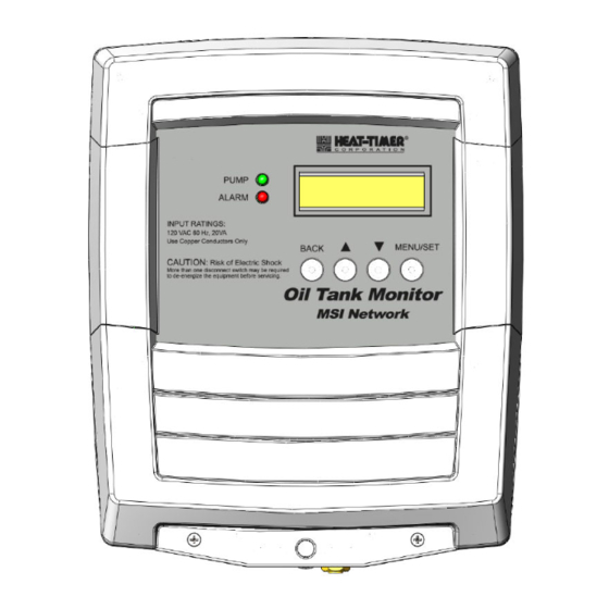
Controls, Indicators, and Connections 3 Controls, Indicators, and Connections Figure 1: MSI OTM Controls, Indicators, and Connections Item Description Item Description Pump Indicator Menu/Set button When lit, indicates the pump is activated. The OTM When pressed, activates programming mode. After Display will also show the level of oil in the tank, in programming mode is activated, pressing this button inches (“Level = xxx”) and “Pump Activates”. will set selected menu options. Refer to “Programming the OTM” on page 10. Alarm Indicator 120Vac Power Input Connection When lit, indicates the oil level has dropped below the (Terminal 1 ‐ Line, Terminal 2 ‐ Neutral, selected alarm level threshold. The OTM Display will Terminal 3 ‐ Earth Ground) also flash “Alarm”. OTM Display Alarm Connection Displays the current level of oil in the tank in normal (Terminal 4 ‐ Alarm Output, Terminal 5 ‐ Alarm Contact) operation, alarm conditions, and available menu selections when in programming mode. Menu “Back” Button MSI Hub Connection When pressed in programming mode, the user is (Terminal 6 ‐ M+, Terminal 7 ‐ M‐) returned to the previous menu screen. To exit programming mode, press the “Back” button until the main screen showing the level of oil remaining in the tank (in inches) is displayed. Menu “Up” and “Down” Navigation Arrows Bulkhead Fitting Used to navigate through the menu selections when ... -
Page 4: Specifications
4 MSI OTM Installation and Operation Manual Specifications Dimensions (W x H x D): . . . . . . . . . . . . . . . . . . . . . . . . . . . . . . . . . . . . . . . . . . . . . . . . . . 8” x 10” x 3.75” (203.2mm x 254mm x 95.25mm) Weight: . . . . . . . . . . . . . . . . . . . . . . . . . . . . . . . . . . . . . . . . . . . . . . . . . . . . . . . . . . . . . . . . . . . . . . . . . . . . . . . . . . . . . . . . . . . . . . . . 4 lb (1.8kg) Power Input: . . . . . . . . . . . . . . . . . . . . . . . . . . . . . . . . . . . . . . . . . . . . . . . . . . . . . . . . . . . . . . . . . . . . . . . . . . . . . . . . . . . . . . . . . . .120Vac 60Hz Max. Input Rating: . . . . . . . . . . . . . . . . . . . . . . . . . . . . . . . . . . . . . . . . . . . . . . . . . . . . . . . . . . . . . . . . . . . . . . . . . . . . . . . . . . . . . . . . . . . . 20VA Output Relays: . . . . . . . . . . . . . . . . . . . . . . . . . . . . . . . . . . . . . . . . . . . . . . . . . . . . . . . . . . . . . . . . . . . . . . . . . . . . . . . . . . . . . . 1 Alarms (SPST) Output Relay Rating: . . . . . . . . . . . . . . . . . . . . . . . . . . . . . . . . . . . . . . . . . . . . . . . . . . . . . . . . . . . . . . . . . . . . . . . 1A Resistive @ 120Vac 60Hz Alarm Setpoint: . . . . . . . . . . . . . . . . . . . . . . . . . . . . . . . . . . . . . . . . . . . . . . . . . . . . . . . . . . . . . . . . . . . . . . . . . . . . . . . . . . . . . .0 to 100 inches Offset: . . . . . . . . . . . . . . . . . . . . . . . . . . . . . . . . . . . . . . . . . . . . . . . . . . . . . . . . . . . . . . . . . . . . . . . . . . –15 to 15 inches (–381mm to 381mm) User Interface: . . . . . . . . . . . . . . . . . . . . . . . . . . . . . . . . . . . . . . . . . . . . . . . . . . . . . . . . . . . . . . . . . . . . . . . . . . . . . . Status Indicators (2 LEDs) Variable Function Buttons (4) Alphanumeric Display (2 x 16) Display Units: Inches Heat‐Timer Corp. 059411-00 Rev. A... -
Page 5: Installation Instructions
Installation Instructions 5 Installation Instructions This section provides the installation instructions for the MSI OTM. The installation process consists of the following basic steps: 1. Selecting appropriate locations and mounting the device(s). 2. Connecting power and communications wiring. 3. Performing an initial startup and configuration of the system. Required Materials (Not Supplied) The following materials/tools are required for installation, but are not supplied: • General tool kit (screwdrivers, wrenches, wire strippers, power drill, etc.) • 1/4” copper compression tee • 1/4” copper tubing (soft) • 18 AWG multi‐conductor, shielded twisted‐pair cable (Belden p/n 8760 or equivalent #18/2 cable) – used for the 24Vac OTM to MSI Hub connection Mounting the MSI OTM 1. Select an appropriate location to mount the Oil Tank Monitor. The location must meet the following minimum requirements: • The location should be between the oil tank being monitored and the control, and must be within 500 feet (152.4 meters) of the MSI Hub. • The mounting surface should be flat and strong enough to hold the weight of the device. • DO NOT mount the device in a location where it will be exposed to extreme heat, cold, humidity, or moisture. 2. Remove the Enclosure Wiring Cover (1) by removing the two lower screws (2) holding it to the base (3), and then remove the Enclosure Display Module (4) by removing the two middle screws (5) holding it to the base. Heat‐Timer Corp. 059411-00 Rev. A... - Page 6 6 MSI OTM Installation and Operation Manual 3. Carefully disconnect the Bulkhead Fitting plastic tubing from the Enclosure Display Module (1) by pressing the small handle on the tubing connector (2). 4. Position the Enclosure base in the desired location, and then secure the base in place using two screws (provided) through the mounting holes (1) on the back of the Enclosure base. 5. Reinstall the Enclosure Display Module using the following steps: a. Reconnect the Bulkhead Fitting plastic tubing by snapping the fitting on the Enclosure Display Module back into the tubing connector (refer to Step 3 above). b. Place the Enclosure Display Module into the base and secure it in place using the middle screws removed in Step 2 above. NOTE: Do not replace the Enclosure Wiring Cover until all wiring is completed. 6. Connect the probe using one of the following methods: • Connecting the Probe to an existing Petrometer 1. Break into the existing tubing running from the oil tank to the Petrometer and install a 1/4” compression tee. 2. Connect 1/4” soft copper tubing from the compression tee to the bulkhead fitting located at the base of the OTM. Do not use teflon tape on the fittings. 3. Tighten the fittings at the compression tee and the OTM bulkhead fitting. CAUTION DO NOT overtighten the bulkhead fitting. Doing so may cause the fitting to rotate. Heat‐Timer Corp. 059411-00 Rev. A...
-
Page 7: Connecting The Wiring
Installation Instructions 7 • Connecting the Probe directly to the Oil Tank 1. Using 1/4” soft copper tubing, connect one end of the tubing to the bottom of the oil tank, and then connect the other end of the tubing to the bulkhead fitting located at the base of the OTM. Do not use teflon tape on the fittings. 2. Tighten the OTM bulkhead fitting. CAUTION DO NOT overtighten the bulkhead fitting. Doing so may cause the fitting to rotate. 7. Continue to “Connecting the Wiring” on page 7 when all devices have been mounted. Connecting the Wiring WARNING ELECTRICAL SHOCK HAZARD! For your safety, to avoid the risk of electric shock, disconnect electrical power to the device before servicing or making any electrical connections. DO NOT re‐connect electrical power until ALL wiring to the MSI OTM is completed. Failure to do so may result in severe personal injury or death. CAUTION When wiring the Oil Tank Monitor, it is important to remember that Class 1 voltages must enter the enclosure through a different knockout than any Class 2 voltage wiring. 1. Connect the power wiring to the Oil Tank Monitor. a. Run the 120Vac, 60Hz power wires through the power knockout of the OTM enclosure. The left‐most knockout is preferred. b. Connect the hot line to terminal “L”. c. Connect the neutral line to terminal “N”. d. The terminal marked “G” (ground) must be connected to earth ground. Heat‐Timer Corp. 059411-00 Rev. A... - Page 8 8 MSI OTM Installation and Operation Manual 2. Connect the MSI Network wiring. NOTE: MSI Network wires can be arranged in any way to the OTM. Multiple network sensors can also be daisy‐chained together to the MSI Hub. a. Run the 24Vac sensor wiring through a knockout on the OTM enclosure (note that it MUST be a different knockout than the one through which the power wiring was run). b. Connect the sensor wiring to terminal 6 (M+) and terminal 7 (M‐) on the OTM, and then to terminal 3 (M+) and terminal 4 (M‐) on the MSI Hub. MSI HUB 3. Connect the Alarm wiring. NOTE: The OTM can be used to activate a Vis‐U‐Larm (925011‐00) when the tank level falls below the selected level. a. Run the alarm wiring through a knockout on the OTM enclosure (note that it MUST be a different knockout than the one through which the power wiring was run). b. Connect the gray and white wire (alarm output connected to one Normally Open [N.O.] relay) to terminal 4 on the OTM. NOTE: The N.O. contact is capable of switching 1 amp resistive at 120Vac. c. Connect the red wire (alarm dry contacts) to terminal 5 on the OTM. 4. After all wiring to the OTM is complete, replace the OTM enclosure wiring cover and secure it in place with two screws. Heat‐Timer Corp. 059411-00 Rev. A...
-
Page 9: Startup Instructions
Startup Instructions 9 Startup Instructions Use the following steps to perform an initial configuration of the MSI OTM. 1. Connect power to the Oil Tank Monitor. The following sequence of events will occur: a. The OTM displays “Heat-Timer Corp. V 1.00 2013” followed by “Oil Tank Level Monitor”. b. The OTM displays “Level= [xxx] ” where [xxx] is the oil level in the tank, in inches. c. After the oil level is displayed, the internal oil pump turns on to update the oil level reading. The OTM displays “Pump activates”. d. After the pump finishes, the OTM updates the display to show the current oil level in the tank. 2. Enter programming mode and configure the following settings (refer to “Programming the OTM” on page 10 for information): • Oil Type – Select the oil type used in the system (Oil #2, Oil #4, or Oil #6). • Bottom Offset – If a petrometer is installed, set the Bottom Offset so the OTM and petrometer display the same oil level. Heat‐Timer Corp. 059411-00 Rev. A... -
Page 10: Detailed Operation
10 MSI OTM Installation and Operation Manual Detailed Operation Control Theory The Oil Tank Monitor measures and displays the number of inches of oil in a tank, and can activate an alarm if the oil level falls below a user‐configured number of inches. The unit is designed to transmit the tank level (via the MSI Hub) to the Platinum Control, which then sends the information to the Internet Control Management System (ICMS). This allows remote users to monitor the level of the tank and send out alarms if the tank level is outside the desired range. The Oil Tank Monitor has a pump for automatic pressure compensation. An internal timer energizes the pump at regular intervals to ensure correct operation. The pump can also be programmed to activate immediately for testing or after maintenance. The Oil Tank Monitor’s internal programming mode allows adjustment of the Alarm value (in inches) and provides an offset for tube placement in the oil tank. Once programmed, these values will not be lost if power is interrupted or lost. The program values are displayed, allowing precise adjustment for each setting. Programming the OTM Figure 2: Oil Tank Monitor User Interface 1. Press the MENU/SET button once to enter programming mode. 2. Use the up/down arrow buttons to navigate through the menu options. When the desired menu option is found, press the MENU/SET button to select the option. Press the BACK button to return to the previous screen. 3. Continue setting programming options using the up/down arrow, MENU/SET, and BACK buttons until all options have been configured. 4. After all options have been configured, press the Back button until the OTM main display is reached, showing the current oil level in the tank (in inches). Heat‐Timer Corp. 059411-00 Rev. A... -
Page 11: Otm Menu Options
Detailed Operation 11 OTM Menu Options Option Displayed as... Description Toggle Pump Manually activates the pump. Selecting the option a second time will Toggle Pump deactivate the pump. This function can be used to test the pump, remove air from the system after maintenance, or to provide a minute‐to‐minute reading of the oil level on the display. Oil Type Specifies the oil type used in the system (Oil #2, Oil #4, or Oil #6). Oil Type Bottom Offset Specifies the oil tank bottom offset (from –15 to 15 inches). Bot. Ofs. The OTM copper tube may not reach the bottom or the tank. This setting ensures the petrometer and the OTM display the same oil level. Alarm Level Specifies the minimum oil level alarm threshold (from 0 to 100 inches, Alr. Level factory setting = 10). If the oil level falls below the specified threshold, the Alarm LED will light and the display will flash “ALARM”. OTM Menu Map Heat‐Timer Corp. 059411-00 Rev. A... -
Page 12: Troubleshooting
12 MSI OTM Installation and Operation Manual Troubleshooting Symptom Possible Cause Recommended Action Oil Tank level: incorrect reading consistent “Offset” value set incorrectly. Change the “Offset” value. across different levels in the tank Oil Tank level: incorrect reading varies Petrometer reading inaccurate. Verify the accuracy of the Petrometer. across different levels in the tank Replace if necessary. Oil Tank level: level drops 1 inch Normal operation. Check the oil level within 1 minute of (2.54cm) after running then stopping the stopping the pump. pump Oil Tank level: level drops 1 inch Air connection(s) leaking. Check all air connections for leakage. (2.54cm) after running then stopping the Tighten connections as necessary. pump Heat‐Timer Corp. 059411-00 Rev. A... -
Page 13: Connection Diagram
Connection Diagram 13 Connection Diagram The following figure shows the basic connections between the oil tanks, MSI OTM, MSI Hub, and an optional petrometer. Refer to “Installation Instructions” on page 5 for more information. Figure 3: MSI OTM – Basic Connection Diagram Heat‐Timer Corp. 059411-00 Rev. A... -
Page 14: Notes
14 MSI OTM Installation and Operation Manual Notes Heat‐Timer Corp. 059411-00 Rev. A... - Page 15 Notes 15 Notes Heat‐Timer Corp. 059411-00 Rev. A...
- Page 16 Heat-Timer Corporation shall not be responsible for any maladjustments of any control installed by Heat-Timer Corporation. It is the user’s responsibility to adjust the settings of the control to provide the proper amount of heat or cooling required in the premises and for proper operation of the heating or cooling system. Heat-...
Need help?
Do you have a question about the MSI OTM and is the answer not in the manual?
Questions and answers