Advertisement
Quick Links
where inspiration flows
Wedmore Road, Cheddar, Somerset, England BS27 3EB
tel 01934 744466
aftersales @ vado.com
www.vado.com
Version 2, 1-12-22
Vado
fax 01934 744345
ZONE
Installation Guide
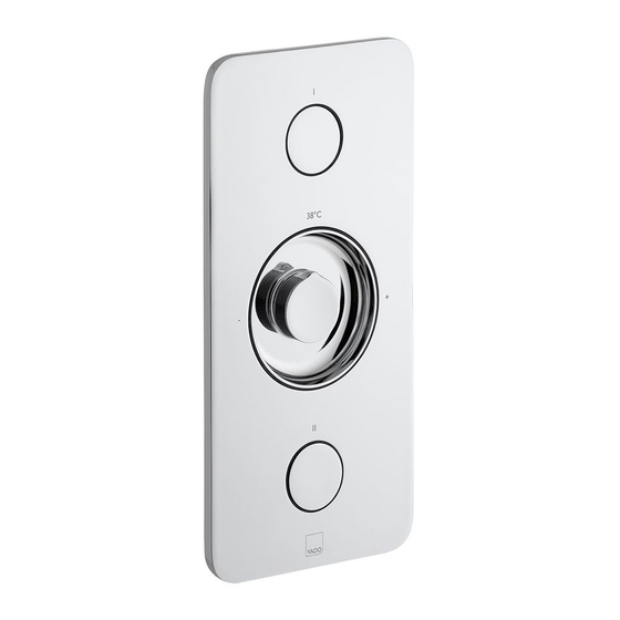
2 way thermostatic shower valve
ZON-128/2-CP
ZON-128/2-H-CP
Note: This product can be fitted horizontally or
vertically. Please ensure the installation corresponds
to the correct orientation. For illustrational purposes
the horizontal fitting is shown throughout, for vertical
installation, refer to page 10.
Keep for future reference
Advertisement

Subscribe to Our Youtube Channel
Related Manuals for VADO ZONE ZON-128/2-CP


Summary of Contents for VADO ZONE ZON-128/2-CP
- Page 1 Wedmore Road, Cheddar, Somerset, England BS27 3EB to the correct orientation. For illustrational purposes tel 01934 744466 fax 01934 744345 the horizontal fitting is shown throughout, for vertical aftersales @ vado.com installation, refer to page 10. www.vado.com Keep for future reference Version 2, 1-12-22...
-
Page 2: General Installation
Important - please read Contents of Packaging Please read these instructions carefully before starting installation and keep for future reference. Installation guide & User manual Remove all packaging and check the product for missing parts or damage before starting installation. Any alterations made to this product and fittings may infringe water regulations and will invalidate the guarantee. - Page 3 Dimensions Installation - Quick guide 160mm 80mm 117mm 238mm 230mm 248mm...
- Page 4 Installation - Quick guide Installation - Quick guide > < 84 mm 84 mm Wall depth Wall depth A+B=C mm Z mm B mm A mm C mm Z mm < 84 mm Wall depth C mm > < > 84 mm 84 mm <...
- Page 5 Installation - Quick guide Temperature Calibrating Note: mixed water temperature at > 84 mm terminal fitting should never exceed Wall depth 46°C. The valve has been factory set under balance pressures and hot water supply at 65°C. When your specific operating conditions are significantly different from the above, the temperature of the water may vary from the setting.
-
Page 6: Vertical Installation
Vertical installation Installation The valve will need to be rotated 90° anti-clockwise. Select the position for the shower valve and offer the shower valve to Min 80mm Max 117mm the wall, make sure the valve is level and mark the 4 fixing points with a pencil. Remove the shower valve from the wall, drill the holes to a suitable depth for Minimum 80mm... - Page 7 Installation Installation Outlet 2 Installation plate Outlet 1 Blanking plug Prongs Cold inlet Hot inlet Connect hot supply to the lower left inlet of the valve and cold supply to the lower Remove the installation plate using the prongs. right inlet. Connect the outlets to the desired channels e.g. shower head and handset. If using an additional module, remove a blanking plug on the desired side using a 12mm allen key.
- Page 8 Installation Installation < Installation 84 mm plate Wall depth Installation B mm A mm Extenders hex socket Installation C mm Measure the distance between the installation plate and the end of the spline adapter (A mm). Measure how far the installation box protrudes from the wall (B mm) and Screw on the extenders from the button connection kits.
- Page 9 Installation Installation < 84 mm Wall depth Y mm X mm Z mm X+Y=Z mm Ensure the extenders are pushed inwards so that the cartridge is in the off position. Remove the extenders. Trim the extenders as per the measured distance (Z mm). Measure to the end of the button extender (X mm).
- Page 10 Installation- for wall depth of up to 84mm Installation- for wall depth of up to 84mm Plate assembly Buttons Friction washer Lip on the inside Place the buttons onto the caps and offer the plate up to the wall. Without fixing the The friction washer is then placed into the central hole of the plate, make sure that the plate, check if when both buttons are installed whether they sit flush with the plate.
- Page 11 Installation- for wall depth of over 84mm Installation- for wall depth of over 84mm Nuts Trim plate Screws Plate assembly Using the four long screws and nuts, screw the trim plate down until the front of the The plate assembly is then located over the middle spline and using the two small trim plate is flush with wall, use the supplied hex key.
- Page 12 Installation Installation Shroud Point on handle Temperature handle The shroud is then placed into the friction washer. Use the handle to fully rotate the spline clockwise. Lift off the handle, and locate it onto the spline adapter so the point is facing the +. Handle Hex key washer...
Need help?
Do you have a question about the ZONE ZON-128/2-CP and is the answer not in the manual?
Questions and answers