Table of Contents
Advertisement
Quick Links
ControlLogix
Voltage/Current Input Module
(Catalog Number 1756-IF8)
To:
Obtain a User Manual
This product also has a user manual (pub. no. 1756-6.5.9). To view it,
visit www.ab.com/manuals or www.theautomationbookstore.com
You can also purchase a printed manual by:
• contacting your local distributor or Rockwell Automation
representative
• visiting www.theautomationbookstore.com and placing
an order
Installation Instructions
Publication 1756-IN040C-EN-P - October 2000
See page:
1
2
3
3
4
5
5
6
8
12
12
14
15
16
16
18
Advertisement
Table of Contents

Related Manuals for Allen-Bradley ControlLogix 1756-IF8


Summary of Contents for Allen-Bradley ControlLogix 1756-IF8
-
Page 1: Table Of Contents
Installation Instructions ControlLogix Voltage/Current Input Module (Catalog Number 1756-IF8) See page: Obtain a User Manual Identify the Module Components Prevent Electrostatic Discharge See Removal and Insertion Under Power (RIUP) Understand Compliance to European Union Directive Note the Power Requirements Install the Module Key the Removable Terminal Block/Interface Module Wire the Module Assemble the Removable Terminal Block and the Housing... -
Page 2: Identify The Module Components
2 ControlLogix Voltage/Current Input Module • calling 800.963.9548 (USA/Canada) or 001.320.725.1574 (outside USA/Canada) Identify the Module Components You received the following components with your order: • 1756-IF8 module • Removable Terminal Block (RTB) door label If you did not receive these components, contact your Rockwell Automation sales office. -
Page 3: Prevent Electrostatic Discharge
ControlLogix Voltage/Current Input Module 3 Prevent Electrostatic Discharge Electrostatic discharge can damage integrated circuits or ATTENTION semiconductors if you touch backplane connector pins. Follow these guidelines when you handle the module: • Touch a grounded object to discharge static potential. •... -
Page 4: Understand Compliance To European Union Directive
Voltage, by applying the safety requirements of EN 61131-2 Programmable Controllers, Part 2 - Equipment Requirements and Tests. For specific information required by EN 61131-2, see the appropriate sections in this publication, as well as the following Allen-Bradley publications: • Industrial Automation Wiring and Grounding Guidelines, publication 1770-4.1 •... -
Page 5: Note The Power Requirements
ControlLogix Voltage/Current Input Module 5 Note the Power Requirements This module receives power from the 1756 chasis power supply and requires 2 sources of power from the backplane: • 150mA at 5.1V dc • 40mA at 24V dc Add this current/power value (1.73W) to the requirements of all other modules in the chassis to prevent overloading the power supply. -
Page 6: Key The Removable Terminal Block/Interface Module
6 ControlLogix Voltage/Current Input Module Key the Removable Terminal Block/Interface Module Wedge-shaped keying tabs and U-shaped keying bands came with your RTB to prevent connecting the wrong wires to your module. Key positions on the module that correspond to unkeyed positions on the RTB. - Page 7 ControlLogix Voltage/Current Input Module 7 A. Remove a length B. Pull the foil shield C. Twist the foil shield D. Attach a ground lug of cable jacket and bare drain and drain wire and apply heat from the wire from the together to form a shrink tubing to the connecting cable.
-
Page 8: Wire The Module
8 ControlLogix Voltage/Current Input Module Wire the Module You can only connect wiring to your module through an RTB or IFM. The example below shows how to wire the module. 1756-IF8 Differential voltage wiring example - 4 channels Channel 0 IN-0 i RTN-0 IN-1... - Page 9 ControlLogix Voltage/Current Input Module 9 1756-IF8 Differential current wiring example - 4 channels Channel 0 IN-0 i RTN-0 IN-1 i RTN-1 IN-2 i RTN-2 Jumper wires Shield IN-3 i RTN-3 ground IN-4 i RTN-4 Channel 3 IN-5 i RTN-5 2-Wire IN-6 i RTN-6 Transmitter...
- Page 10 10 ControlLogix Voltage/Current Input Module 1756-IF8 Single-ended voltage wiring example Channel 0 IN-0 i RTN-0 IN-1 i RTN-1 – IN-2 i RTN-2 IN-3 i RTN-3 Shield ground Channel 1 IN-4 i RTN-4 IN-5 i RTN-5 – IN-6 i RTN-6 IN-7 i RTN-7 Not used Not used...
- Page 11 ControlLogix Voltage/Current Input Module 11 1756-IF8 Single-ended current wiring example Channel 0 IN-0 i RTN-0 IN-1 i RTN-1 Jumper IN-2 i RTN-2 wires Shield ground IN-3 i RTN-3 Channel 5 IN-4 i RTN-4 2-Wire IN-5 i RTN-5 Transmitter IN-6 i RTN-6 IN-7 i RTN-7 Not used...
-
Page 12: Assemble The Removable Terminal Block And The Housing
12 ControlLogix Voltage/Current Input Module Assemble the Removable Terminal Block and the Housing 1. Align the grooves at the bottom of the housing with the side edges of the RTB. Groove Side edge of the RTB Groove Strain relief area Side edge of the RTB 2. - Page 13 ControlLogix Voltage/Current Input Module 13 Before installing the RTB, make certain: • field-side wiring of the RTB has been completed. • the RTB housing is snapped into place on the RTB. • the RTB housing door is closed. • the locking tab at the top of the module is unlocked. 1.
-
Page 14: Check The Indicators
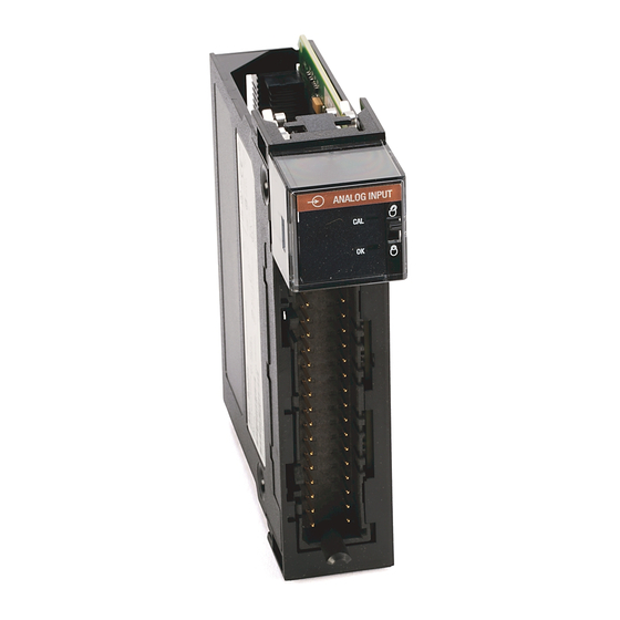
14 ControlLogix Voltage/Current Input Module Check the Indicators The indicators show CAL status (green) and a bi-colored LED for module "OK" (red/green). ANALOG INPUT 20962-M During power up, an indicator test is done and the following occurs: • The "OK" indicator turns red for 1 second and then turns to flashing green if it has passed the self-test. -
Page 15: Remove The Removable Terminal Block From The Module
ControlLogix Voltage/Current Input Module 15 Remove the Removable Terminal Block from the Module Shock hazard exists. If the RTB is removed from WARNING the module while the field-side power is applied, the module will be electrically live. Do not touch the RTB’s terminals. -
Page 16: Remove The Module
16 ControlLogix Voltage/Current Input Module Remove the Module 1. Push in top and bottom locking tabs. 2. Pull module out of the chassis. 20856–M 20857–M 1756-IF8 Specifications Number of Inputs 8 single ended, 4 differential or 2 differential (high speed) Module Location 1756 ControlLogix Chassis Backplane Current... - Page 17 ControlLogix Voltage/Current Input Module 17 Calibrated Accuracy at 25°C Better than 0.05% of range - voltage Better than 0.15% of range - current Calibration Interval Twelve months typical Input Offset Drift with 45µV/degree C Temperature Gain Drift with Temperature 15 ppm/degree C - voltage 20 ppm/degree C - current Module Error over Full 0.1% of range - voltage...
-
Page 18: Hazardous Location Information
18 ControlLogix Voltage/Current Input Module Additional Notes The ControlLogix system must be mounted within a suitable enclosure to prevent personal injury resulting from accessibility to live parts. The interior of this enclosure must be accessible only by the use of a tool. This industrial control equipment is intended to operate in a Pollution Degree 2 environment, in overvoltage category II applications, as defined in IEC publication 664A, at altitudes up to 2000 meters without derating. - Page 19 ControlLogix Voltage/Current Input Module 19 Informations sur l’utilisation de cet équipement en environnements dangereux : Les produits marqués « CL I, DIV 2, GP A, B, C, D » ne conviennent qu’à une utilisation en environnements de Classe I Division 2 Groupes A, B, C, D dangereux et non dangereux.
- Page 20 Rockwell Automation Support Rockwell Automation provides technical information on the web to assist you in using its products. At http://support.rockwellautomation.com, you can find technical manuals, a knowledge base of FAQs, technical and application notes, sample code and links to software service packs, and a MySupport feature that you can customize to make the best use of these tools.
Need help?
Do you have a question about the ControlLogix 1756-IF8 and is the answer not in the manual?
Questions and answers