Table of Contents
Advertisement
Quick Links
Advertisement
Table of Contents

Related Manuals for Oxford Optronix OXYLITE


Summary of Contents for Oxford Optronix OXYLITE
- Page 1 USER MANUAL...
- Page 2 Banbury Business Park Adderbury OX17 3SN United Kingdom t: +44 (0)1235 821 803 Sales www.oxford-optronix.com sales@oxford-optronix.com Support www.oxford-optronix.com/support/oxylite-support support@oxford-optronix.com OxyLite™ and OxyFlo™ are registered trademarks of Oxford Optronix Ltd. © Oxford Optronix Ltd 2023. All rights reserved. Revision 1.4 | October 2023...
-
Page 3: Table Of Contents
FCC Compliance ......................4 Regulatory Compliance ..................... 4 OxyLite Symbols ......................5 Definitions ......................... 5 Summary of Warnings for the OxyLite Monitor ............6 Summary of Cautions for the OxyLite Monitor ............6 Summary of Cautions for OxyLite Sensors ..............6 NTRODUCTION General Description .................... - Page 4 Table 3: Display messages ...................... 18 Table 4: Analogue output unit conversion ................23 Table 5: Diagnostic analogue output voltages ................ 23 Table 6: Common sensor fault codes ..................27 Table 7: Technical specifications for OxyLite ................32 Revision 1.4 | October 2023...
-
Page 5: Safety Information
OxyLite is suited to the determination of tissue or cell culture hypoxia as the measurement technique is particularly sensitive at low tissue pO OxyLite may be used in conjunction with OxyFlo, a laser Doppler blood flow monitor that is intended for monitoring microvascular blood perfusion in tissue. The combination of these two fibre optic measurement systems provides simultaneous tissue blood flow and oxygenation data. -
Page 6: Oxylite Symbols
OxyLite User Manual Low Voltage Directive (LVD) This equipment meets European Parliament and Council Low Voltage Directive 2014/35/EC, and equivalent UKCA Directive SI 2016 No. 1101 (The Electrical Equipment (Safety) Regulations 2016). Hazardous Substances (RoHS) This equipment meets European Parliament and Council Directive 2011/65/EU on the restriction of the use of certain hazardous substances in electrical and electronic equipment, and equivalent UKCA Directive UK SI 2012 No. -
Page 7: Summary Of Warnings For The Oxylite Monitor
WARNING Summary of Cautions for the OxyLite Monitor DO NOT attempt to operate the OxyLite in the vicinity of imaging or therapeutic equipment that emits ionising radiation or produces a strong magnetic field as the performance of the monitor may be CAUTION affected. - Page 8 For safe storage of OxyLite sensors always refit the protective black cover when a sensor is not in use. CAUTION DO NOT drop, stretch or ‘kink’ any part of an OxyLite sensor. Permanent damage may result. CAUTION Attempting to disconnect the sensor by pulling the cable sleeving instead of the front of the sensor connector may cause irreparable damage to the sensor.
-
Page 9: Introduction
‘EEPROM’ electronic chip integral to the sensor connector; these data are automatically read by and transferred to the OxyLite monitor upon connection. Available OxyLite functionality is controlled via a functions button at the rear of the monitor. Revision 1.4 | October 2023... -
Page 10: Key Features
Data logging The OxyLite™ offers a choice of traditional 0-5V analogue outputs and a digital (USB) data output that supports direct streaming to the popular LabChart® Pro charting software by ADInstruments. After installing a complimentary add-on, LabChart® will automatically identify the specific type and model of monitor and pre-load all the necessary configuration and channel settings, providing the ultimate in ‘plug and play’... -
Page 11: The Oxylite Monitor
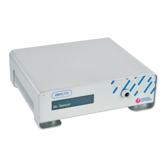
Optional extended warranty packages including preventative maintenance servicing are also available for additional peace of mind. The OxyLite Monitor Figure 1: OxyLite front view 1. Power-on indicator light 2. Alphanumeric OLED display 3. Sensor connector... -
Page 12: Oxylite Sensors
OxyLite Sensors Introduction A comprehensive range of sensors are available for use with the OxyLite monitor (as listed on our website, here). In addition, there are sensors available for the simultaneous measurement of microvascular blood perfusion when OxyLite is used in conjunction with its counterpart, the OxyFlo. -
Page 13: Figure 3: Oxygen Or Oxygen/Temperature Sensor Presentation
OxyLite User Manual from the site of oxygen measurement and provide automatic temperature compensation of the oxygen measurement. The temperature sensors are polyurethane-coated T-type thermocouples that have a diameter of approx. 100 µm. The number of plugs on a sensor is dependent on the number of parameters being measured. -
Page 14: Figure 4: Combined Oxygen/Blood Flow Sensor Presentation
(plus, where specified, a thermocouple temperature sensor). Sensor calibration All OxyLite sensors are individually pre-calibrated prior to dispatch. Sensor calibration data is stored within integrated ‘EEPROM’ electronic chips to provide true ‘plug and play’ convenience. The electronic chip contains sensor-specific calibration information which is read and loaded automatically by the monitor upon connection. -
Page 15: Accessories
OxyLite User Manual OxyLite sensors are NOT approved for use on human subjects. CAUTION DO NOT drop, stretch or ‘kink’ any part of an OxyLite sensor. Permanent damage may result. CAUTION Attempting to disconnect the sensor by pulling the cable sleeving instead of the front of the sensor connector may cause irreparable damage to the sensor. -
Page 16: Monitor Setup And Use
Ensure that the power on/off switch at the rear of the OxyLite is in the OFF (0) position. Plug the IEC power cable into the IEC mains inlet at the rear of the OxyLite and the plug end of the IEC power cable into a wall mains supply. -
Page 17: Display Messages
CAUTION Display Messages The OxyLite front panel displays the pO and temperature measurements when a sensor is connected and in use. Other messages, including error messages are also displayed to the user. A list of messages and their meaning is provided below:... - Page 18 (factory set) date and time (GMT). Analogue Time hh:mm output during this time is 0V (0% scale). There is no sensor connected to the OxyLite but the monitor has completed its boot sequence and is ready for use. Analogue output during No Sensor this time is -2.5V (-50% scale).
-
Page 19: The Set Button
Table 3: Display messages The SET button OxyLite functionality is controlled via a SET button at the rear of the monitor (see figure 2). Pressing the button when no sensor is connected allows the oxygen units to be selected from a choice of mmHg or kPa. - Page 20 (1)’ error message, and the measurement will cease. The OxyLite will not accept a sensor that has exceeded its 2-year shelf life. If a sensor is connected after the shelf life expiry date the instrument will display a ‘Sensor Expired (1)’...
-
Page 21: Placement Of Sensors In Vivo Or In Vitro
At 50 hours of accumulated usage the monitor will display a ‘Sensor Expired (3)’ error message, and the measurement will cease. The OxyLite will not accept a sensor that has exceeded its 48 + 2-hour accumulated usage limit. If a sensor is connected after this limit has been exceeded, the instrument will display a ‘Sensor Expired (1)’... -
Page 22: Temperature Compensation
Temperature compensation can also be achieved by manual temperature control using the SET button at the rear of the OxyLite monitor. This allows the use of less costly oxygen-only sensors in certain circumstances. Manual temperature control may suffice in situations where the temperature of the monitoring site or fluid is stable and known to within ±2 -... -
Page 23: Digital (Usb) Data Output
Alternatively the Oxford Optronix Device Enabler is available for download from the ‘Downloads’ section of the ADInstruments website. Dedicated instructions for setting up LabChart Pro for recording from OxyLite monitors can be found on our support site (https://www.oxford-optronix.com/support/oxylite-support). *Notes: PC/Windows platforms supported only at this time; LabChart 8.0.4 or later required. -
Page 24: Table 4: Analogue Output Unit Conversion
OxyLite User Manual Generic female-female BNC cables (optionally available from Oxford Optronix; product ‘OLO-BNC’) provide compatibility with the vast majority of data acquisition systems. The following table summarizes the unit conversion parameters required for data acquisition via the analogue outputs (factory defaults):... -
Page 25: Care Of Oxy Lite
To avoid the risk of electric shock or shorts, do not spray, pour or spill any liquid in or on the OxyLite. WARNING The OxyLite monitor should be stored between 10°C to 40°C. If returning from extremes of temperature, the unit should be allowed to acclimatise at room temperature for 30 minutes before use. -
Page 26: Cleaning, Disinfection And Sterilization Of Sensors
Cleaning OxyLite sensors are manufactured and packed in a controlled (clean) environment. The tips of OxyLite sensors can be cleaned after use by gentle wiping with water, or saline-soaked cotton wool / cotton gauze. The oxygen sensing tips are fragile and can be damaged by attempts to clean them without due care and attention. -
Page 27: Troubleshooting And Maintenance
AINTENANCE Troubleshooting If you experience a problem using the OxyLite that you are unable to correct by following the suggestions below or by reconnecting the sensor(s) and/or turning off and turning back on the monitor, please contact Oxford Optronix technical support (see p2 of this document). -
Page 28: Table 6: Common Sensor Fault Codes
(where used in vivo). For example, the force exerted by the tip of an OxyLite sensor can easily exceed capillary closing pressure. Low pO readings will result if this is the case. To overcome this situation, support the sensor cable and sensor tip area as neutrally as possible in such a way that the sensor is not exerting forward or lateral forces on the tissue. - Page 29 1) Turn equipment off in the vicinity of the monitor to isolate the equipment that may be generating the electro-magnetic interference. 2) Relocate the other device(s). 3) Increase the separation between the potentially interfering equipment and the OxyLite monitor. Revision 1.4 | October 2023...
-
Page 30: Simple Sensor Functionality / Calibration Check
The monitor should be inspected regularly for signs of wear and tear. The OxyLite monitor is supplied with a 2 year warranty. Please refer to the Terms and Conditions of the Warranty at the end of this user manual for further details. -
Page 31: Returning The Oxylite Monitor
Declaration form MUST be obtained prior to shipping the equipment. Pack the OxyLite in its original shipping carton where available. If the original carton is not available, pack the OxyLite in a suitably sized STURDY cardboard box ensuring that it is surrounded on ALL sides by at least 10 cm (4”) of tightly packed polystyrene chips, bubble... -
Page 32: Technical Specifications
OxyLite User Manual 6. T ECHNICAL PECIFICATIONS Physical Dimensions 90mm (H) x 250mm (W) x 220mm (D) Weight 2Kg / 4.5lbs Operating temperature 10 - 30°C Operating humidity 0 – 70% (non-condensing) Power requirements VAC 100-240V, 50-60Hz, 30W max. Fuse rating 2 x T1.6A anti-surge... -
Page 33: Table 7: Technical Specifications For Oxylite
Sensor longevity 48 hours accumulated usage Analogue data output range 0 – 5V (0 – 200mmHg / 0 – 50ºC) Analogue data output rate Table 7: Technical specifications for OxyLite Specifications subject to change without notice. Revision 1.4 | October 2023... -
Page 34: Warranties
Sensors are warranted for a single use only. Oxford Optronix Ltd. is not liable under this warranty for defects arising from more than one insertion (or use) in vivo, and/or for continuous/accumulated operation in excess of 48 hours at the default sampling rate, and/or for operation in excess of 12 months from factory calibration. - Page 35 OxyLite User Manual otherwise) in respect of defects in the Products or failure to correspond to specification or for any injury, damage or loss resulting from such defects or failure. In no event shall any breach of contract on our part or tort (including negligence) or failure of any kind on our part give rise to any liability for loss of revenue or loss of profits or any other consequential or indirect loss or damage arising from any cause whatsoever.
Need help?
Do you have a question about the OXYLITE and is the answer not in the manual?
Questions and answers