
Related Manuals for Oxford Optronix OxyFlo Pro


Summary of Contents for Oxford Optronix OxyFlo Pro
- Page 1 OxyFlo Pro User Manual User Manual For models OxyFlo™ Pro OxyFlo™ Pro XL Continuous laser Doppler blood flow monitoring Revision 1.1 | May 2015...
- Page 2 +44 (0)1235 821 678 Primary website: www.oxford-optronix.com Sales email: sales@oxford-optronix.com Support website: www.oxford-optronix.com/support/supp_oxyflo.htm Support email: support@oxford-optronix.com OxyLite™ and OxyFlo™ are registered trademarks of Oxford Optronix Ltd. © Oxford Optronix Ltd. 2015. All rights reserved. Revision 1.1 | May 2015...
-
Page 3: Table Of Contents
Laser Safety ................... 6 OxyFlo Pro Symbols ..............6 Definitions ..................7 Summary of Warnings for the OxyFlo Pro Monitor ......8 Summary of Cautions for the OxyFlo Pro Monitor......9 1.10 Summary of Cautions for OxyFlo Pro Probes ......10 1.11... - Page 4 Figure 1: Front view of the OxyFlo Pro............16 Figure 2: Rear view of the OxyFlo Pro ............17 Figure 3: Side-view of OxyFlo Pro, showing open probe connector bay ... 18 Figure 4: The OxyFlo Pro universal AC adapter........18 Figure 5: An OxyFlo Pro probe..............
-
Page 5: Safety Information
Contra-Indications The OxyFlo Pro is purely for laboratory, industrial and research use and is NOT a medical device. The OxyFlo Pro does NOT possess regulatory approvals for use with human subjects or patients. -
Page 6: Emc Compliance - Ec Declaration Of Conformity
WARNING OxyFlo Pro is classified as a Class 1 Laser Product in accordance with the European Standard EN 60825-1:1994 and 21 CFR 1040.10 and 1040.11. In accordance with the standard, the back panel of the monitor carries the... -
Page 7: Definitions
Alternating current Direct current Digital output Analogue outputs Table 1: OxyFlo Pro symbols Definitions A warning indicates the possibility of injury to the operator. WARNING A caution indicates a condition that may lead to equipment damage and/or malfunction. -
Page 8: Summary Of Warnings For The Oxyflo Pro Monitor
OxyFlo Pro User Manual Summary of Warnings for the OxyFlo Pro Monitor Do not attempt to open the OxyFlo Pro. There are no user- serviceable parts inside. There is a risk of electrical shock or other injury or permanent damage to the monitor. -
Page 9: Summary Of Cautions For The Oxyflo Pro Monitor
To avoid damage, do not spray, pour or spill any liquid on the touch screen display. CAUTION DO NOT attempt to operate the OxyFlo Pro in the vicinity of imaging or therapeutic equipment that emits ionising radiation or produces a strong magnetic field as the performance of the monitor may be affected. -
Page 10: Summary Of Cautions For Oxyflo Pro Probes
CAUTION the cable from the probe ends or connectors. OxyFlo Pro probes are NOT approved for use on patients. CAUTION DO NOT drop, apply tension or ‘kink’ any part of an OxyFlo Pro probe. -
Page 11: Summary Of Cautions For Probe Calibration
OxyFlo Pro User Manual 1.11 Summary of Cautions for Probe Calibration It is essential that the calibration procedure is performed on a stable and vibration-free surface. Any movement or vibration during the calibration procedure - however slight - is likely to CAUTION result in a failed calibration. -
Page 12: Introduction
2. I NTRODUCTION General description The OxyFlo Pro is a microvascular blood flow monitor that is capable of monitoring red blood cell (erythrocyte) perfusion in the microcirculation of a tissue. The monitor uses a technique referred to as Laser Doppler Flowmetry (LDF), an established and reliable method for the measurement of blood perfusion in microvascular research. - Page 13 (e.g. comparison of pathological versus control tissue sites). Upgradeable The OxyFlo Pro dual-channel model can be factory upgraded to the 4- channel OxyFlo Pro XL device. Multi-parameter monitoring Our OxyFlo Pro blood flow monitors are designed specifically to be...
-
Page 14: Laser Doppler Flowmetry And The Oxyflo Pro
Measurement parameters generated by the OxyFlo Pro The blood flow (BPU) parameter The primary function of the OxyFlo Pro is to produce a tissue blood flow output signal that is proportional to the red blood cell perfusion (or flux) in the area of tissue being investigated. - Page 15 OxyFlo Pro User Manual For the OxyFlo Pro, tissue blood flow is indicated in relative units called Blood Perfusion Units (BPU). All OxyFlo Pro monitors have been calibrated with a constant, known motility standard so that, for a given blood flow situation, all OxyFlo Pro probes will read the same value of blood flow expressed in BPU.
-
Page 16: The Oxyflo Pro Monitor
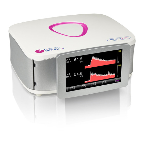
The OxyFlo Pro Monitor Figure 1: Front view of the OxyFlo Pro 1. Power-on indicator light. 2. Sensor connector bay (one on each side for OxyFlo Pro XL). 3. Touch-screen display (with adjustable viewing angle). Revision 1.1 | May 2015... -
Page 17: Figure 2: Rear View Of The Oxyflo Pro
2. Low voltage power inlet (use ‘NX-PSU’ universal AC Adapter only) 3. Analogue output connectors: Ch 1 / Ch 2 (common to all OxyFlo Pro models) Ch 3 / Ch 4 (OxyFlo Pro XL model only) 4. USB serial output for optional direct data streaming to LabChart® Pro 5. -
Page 18: Figure 3: Side-View Of Oxyflo Pro, Showing Open Probe Connector Bay
Figure 4: The OxyFlo Pro universal AC adapter NOTE: Use ONLY the universal AC adapter provided by Oxford Optronix. Failure to do so may result in irreparable damage to the OxyFlo Pro monitor. Revision 1.1 | May 2015... -
Page 19: Oxyflo Pro Probes
Introduction A comprehensive range of Laser Doppler probes is available for use with the OxyFlo Pro monitor, a description of which can be found on our website (www.oxford-optronix.com). All probes are comprised of a pair of 125 μm optical fibres, which are used to direct low power laser light to and from the tissue. - Page 20 CAUTION the cable from the probe ends or connectors. The optical fibres used in OxyFlo Pro probes consist of glass with a diameter of 125 µm. The fibres are flexible and can be bent, however it is recommended that they are not subjected CAUTION to bends with a radius of less than 30mm.
-
Page 21: Accessories
OxyFlo Pro User Manual Accessories The following accessories are available from Oxford Optronix Ltd. for use with the OxyFlo Pro; Product Code Product Description CAL KIT Calibration kit for LDF probes and MSFD NX adapter Double-sided adhesive rings for surface LDF probes. -
Page 22: Monitor Setup And Use
Unpacking and Inspection Immediately notify Oxford Optronix Ltd. or your local distributor if the outer packaging or carton is wet or damaged in any way. Unpack the OxyFlo Pro and its components, ensuring that all items listed on the enclosed packing list / dispatch note are present. - Page 23 3.4). Connecting the NX-PSU universal AC adapter to the DC POWER IN inlet at the rear of the OxyFlo Pro, having already powered it via its On/Off switch MAY trigger the surge protection circuit within the OxyFlo Pro. If the OxyFlo Pro...
-
Page 24: Connecting / Disconnecting Probes
Disconnect by twisting the front portion of the probe connector anti-clockwise, in the direction of the ‘Release’ arrow printed on the connector. NOTE: OxyFlo Pro monitors shipped prior to May 2015 will only function if pairs of connectors are occupied. An optional ‘interlock adapter’ may be used to occupy the unused channel where the user wishes to use an odd number of probes (one or three). -
Page 25: The Touch-Screen Display
Figure 7: The touch screen display with no probes connected Following monitor start up, the display will initially show the default screen (OxyFlo Pro XL model in this example). Figure 8: Touch screen display with 2 probes connected The screen will concurrently display a trace and a numerical value of blood flow for each probe connected, as in the example above. -
Page 26: Figure 9: The Touch Screen Settings Toolbar
OxyFlo Pro User Manual Description of icons: The toolbar confirms the recognised numerical ‘ID’ for connected probes, per channel. Touch to display the probe status dialogue (figure 10). Touch to display the settings toolbar (see figure 9). Touch to toggle x-axis compression. -
Page 27: Table 4: Touch Screen Settings Toolbar Icons
(default is 5V = 5000 BPU). Touch this icon again to display the secondary parameter selection screen. The OxyFlo Pro will output the Flow parameter on the first of two outputs; the second output is selectable (Backscatter, Raw and ART - refer to section 2.4). -
Page 28: Figure 10: The Touch Screen Probe Status Dialogue
OxyFlo Pro User Manual Figure 10: The touch screen probe status dialogue Probe status and calibration information is displayed by selecting the appropriate channel/probe from the toolbar. Refer to the table below and Troubleshooting for probe warnings and errors. Description of probe status dialogue icons: Indicates probe calibration date. -
Page 29: Probe Calibration
Table 5: Probe status dialogue icons Probe Calibration The OxyFlo Pro monitor is designed to automatically recognise and apply the correct calibration coefficients when probes are connected. Probes purchased with a monitor will be calibrated at the factory. Since the... - Page 30 OxyFlo Pro User Manual To use the same probe in multiple channels, the calibration procedure must be repeated in each individual channel. Every probe features a probe ID number (between 1 and 26) that the monitor ‘reads’ each time the probe is connected. This is confirmed on the display toolbar and on the probe status dialogue.
- Page 31 OxyFlo Pro User Manual Keep the active probe surface or probe tip away from the edges or the bottom of the bottle. The probe should be supported in such a way that it does not swing or move whilst in the solution.
- Page 32 OxyFlo Pro User Manual A visual reminder is displayed that the probe needs to be in the calibration solution, which will be accompanied by an audible double ‘beep’ every 2 seconds. 7. Touch the CAL button a second time to trigger the calibration. A 5s continuous ‘beep’...
-
Page 33: Table 6: Calibration Error Codes
OxyFlo Pro User Manual status dialogue will display a cross against the calibration data icon and against the calibration success icon. Touching the dialogue will display a further error screen confirming the calibration error number. There are 6 error codes, as follows:... -
Page 34: Placement Of Probes
OxyFlo Pro User Manual Do not dilute the motility standard. CAUTION It is important that all probes to be used with any one OxyFlo Pro monitor have different probe identification numbers in order to prevent possible probe calibration errors. Please CAUTION contact technical support for advice. -
Page 35: Digital (Usb) Data Output
Compatibility requires a dedicated and free software Add-on for LabChart (the ‘Device Enabler’*), which supports automatic recognition of the Oxford Optronix monitor, the use of multiple Oxford Optronix monitors simultaneously and provides a choice of pre- loaded configuration settings specifically tailored to our monitors. -
Page 36: Analogue Data Outputs
The dual-channel OxyFlo Pro requires one such cable (carrying data for channels 1 and 2), while the 4-channel OxyFlo Pro XL model requires two such cables (carrying data for channels 1 and 2, and 3 and 4, respectively). -
Page 37: Table 7: Parameter Identification On Analogue Output Data Cable
Table 7: Parameter identification on analogue output data cable The following table summarizes the unit conversion parameters required for data acquisition via the analogue outputs at the rear of the OxyFlo Pro monitor when using third-party data recorders (factory defaults shown):... -
Page 38: Care Of Oxy Flo Pro
Handling and Storage of Probes The optical fibres used within the OxyFlo Pro probes consist of glass, with a diameter of 125μm. The fibres are flexible and can be bent. However, it is recommended that they are not subjected to bends with a radius less than 30mm. -
Page 39: Cleaning, Disinfection And Sterilization Of Probes
Dust can be removed from the connectors using a good quality ‘air-duster’. OxyFlo Pro probes should be stored, with the probe cable carefully coiled to avoid ‘kinks’, in the dedicated protective case in which they are supplied. -
Page 40: Disposal Of Probes
CAUTION Disinfection OxyFlo Pro probes can be disinfected by immersion of the probe end and cable in either 2% gluteraldehyde or in 70% alcohol (industrial methylated spirit, IMS or isopropyl alcohol IPA) in water. The disinfectant manufacturer’s recommended immersion times should be used. -
Page 41: Troubleshooting And Maintenance
Was your monitor manufactured prior to May 2015? If so it may only function if pairs of probes are plugged into the monitor (i.e. into channels 1 & 2 for the OxyFlo Pro and into channels 1 & 2 and/or channels 3 & 4 for the OxyFlo Pro XL). - Page 42 ‘Temp out of Range’ will appear on the display. If this occurs check that the fan at the rear of the OxyFlo Pro is not obstructed and/or move the instrument to a cooler location. Analogue outputs will continue but the trend values will not appear on the display.
- Page 43 OxyFlo Pro User Manual condition may no longer be within the calibrated tolerance of the system and should be interpreted with caution. If the ambient temperature is ‘normal’ (typically 18-25ºC) and this message occurs repeatedly soon after power-on, then a fault may have occurred and you should contact technical support for further advice.
- Page 44 The OxyFlo Pro may not therefore be suited to the non-continuous or repeated assessment of changes in tissue blood flow over chronic time...
-
Page 45: Simple Probe Integrity Check
The calibrated zero reading has been obtained by calibrating the system against a special static scattering material where no movements occur. In such cases the back-scattered light processed by the OxyFlo Pro contains no Doppler shifted frequency components and a true zero is obtained. In a true physical sense, ‘noise’... -
Page 46: Maintenance And Servicing
The monitor should be inspected regularly for signs of wear and tear. The OxyFlo Pro monitor is supplied with a 2 year warranty. Please refer to the Terms and Conditions of the Warranty at the end of this document for further details. - Page 47 Use a recognized international courier company for the return of product to Oxford Optronix (e.g. UPS, FedEx, DHL etc). Oxford Optronix will not accept responsibility for any loss or damage to goods shipped to us, howsoever caused. Revision 1.1 | May 2015...
-
Page 48: Technical Specifications
200ms (Flow); 200ms (Backscatter); 5ms (Raw); 5s (ART) (filtering) Display update time (numerical) 2s (5s rolling averaged) Probe identification Automatic; monitor stores one-time calibration Factory or user-calibrated using Oxford Optronix motility Probe calibration standard Zeroing Automatic, controlled Default analogue data output... -
Page 49: Warranty
Operating or User Instructions for a period of 24 months from the date of purchase. Oxford Optronix Ltd’s sole obligation shall be to repair or to replace at Oxford Optronix’ option, FOB its factory, without charge, any part(s) that prove defective within the warranty period.
Need help?
Do you have a question about the OxyFlo Pro and is the answer not in the manual?
Questions and answers