Table of Contents
Advertisement
48XP(N)
Single- -Packaged Gas Furnace/Air Conditioner
System with Puronr (R- -410A) Refrigerant
Single- - And Three- -Phase Units Sizes 024- -060
NOTE:
Read the entire instruction manual before starting the
installation.
NOTE:
Installer: Make sure the Owner's Manual and Service
Instructions are left with the unit after installation.
TABLE OF CONTENTS
. . . . . . . . . . . . . . . . . . . . . . . . . . . . . . . . . .
. . . . . . . . . . . . . . . . . . . . . . . . . . . . . . . . .
. . . . . . . . . . . . . . . . . . . . . . . . . . . . . . . . . . .
. . . . . . . . . . . . . . . . . . . . . . . . . . . . . . . .
. . . . . . . . . . . . . . . . . . . . . . . . . . . . . .
. . . . . . . . . . . . . . . . . . . . . . . . . . . . . . . . . . . . .
. . . . . . . . . . . . . . . . . . . . . . . . . . . . . . . . . . . .
. . . . . . . . . . . . . . . . . . . . . . . . . . . . . . . . .
. . . . . . . . . . . . . . . . . . . . . . . . . . .
. . . . . . . . . . . . . . . . . . . . . . . . . . . . . . . .
. . . . . . . . . . . . . . . . . . . . . . . . . . . . . . . .
. . . . . . . . . . . . . . . . . . . . . . . . . . . . . . . . . .
. . . . . . . . . . . . . . . . . . . . . . . . . . . . . . . . .
. . . . . . . . . . . . . . . . . . . . . . . . . . . .
. . . . . . . . . . . . . . . . . . . . . . . . . . . . . . . . . . . . .
. . . . . . . . . . . . . . . . . . . . . . . . . . . . . . . . . .
. . . . . . . . . . . . . . . . . . . . . . . . . .
. . . . . . . . . . . . . . . . . . . . . . . . . . . . . . . . . .
. . . . . . . . . . . . . . . . . . . . . . . . . . . . . . . . . . . .
. . . . . . . . . . . . . . . . . . . . . . . . . .
. . . . . . . . . . . . . . . . . . . . . . . . . . . . . . .
. . . . . . . . . . . . . . . . . . . . . . . . . . . . . . .
. . . . . . . . . . . . . . . . . . . . . . . . . . . .
. . . . . . . . . . . . . . . . . . . . . . . . . . . . . . . .
. . . . . . . . . . . . . . . . . . . . . . . . . . . . . . . .
. . . . . . . . . . . . . . . . . . . . . . . . . . . . . . .
. . . . . . . . . . . . . . . . . . . . . . . . . . . . . . . . . . . . . . .
. . . . . . . . . . . . . . . . . . . . . . . . . . . . .
Installation Instructions
PAGE
. . . . . . . . . . . . . . . . . . . . . . . .
. . . . . . . . . . . . . . . .
. . . . . . . . . . . . . . . . . . . . . . . . . .
. . . . . . . . . . . . . . . . . . . . . . .
. . . . . . . . . . . . . . . . . . . . . . .
. . . . . . . . . . . . .
. . . . . . . . . . . . . . . . . . . . . .
14- -21
. . . . . . . . . . . . . . . . . . . . . . . .
. . . . . . . . . . . . . . . . . . . . . . . .
. . . . . . . . . . . . . . . . . . . . .
. . . . . . . . . . . . . . .
. . . . . . . . . . . . . . . . . . . . .
. . . . . . . . . . . . . . . . . . . .
. . . . . . . . . . . . . . .
. . . . . . . . . . . . . . .
. . . . . . . . . . .
. . . . . . . . . . . .
22- -25
. . . . . . . . . . . . . . . . . . . . . . .
1
2
2- -13
2
2
2
2
2
2
2
2
2
4
6
7
7
9
9
10
10
11
11
11
. . . . . . . . . . . . . . . . . . . . . . . . . . . . . . . . . . . . . .
14
14
14
. . . . . . . . . . . . . . . . . . . . . . . . . . . . . . . . . . . . . . .
14
14
15
15
15
SAFETY CONSIDERATIONS
15
Installation and servicing of this equipment can be hazardous due
16
to mechanical and electrical components. Only trained and
16
qualified personnel should install, repair, or service this
16
equipment.
16
Untrained personnel can perform basic maintenance functions
17
such as cleaning and replacing air filters. All other operations
17
must be performed by trained service personnel. When working
17
21
on this equipment, observe precautions in the literature, on tags,
and on labels attached to or shipped with the unit and other safety
21
precautions that may apply.
22
Follow all safety codes. Installation must be in compliance with
22
local and national building codes. Wear safety glasses, protective
22
clothing, and work gloves. Have fire extinguisher available. Read
these instructions thoroughly and follow all warnings or cautions
included in literature and attached to the unit.
1
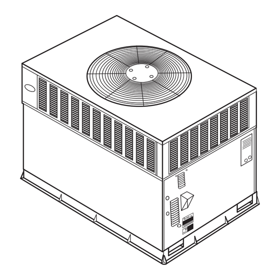
Fig. 1 - - Unit 48XP
. . . . . . . . . . . . . . . . . . . . . . . . . . .
. . . . . . . . . . . . . . . . . . . . . . . . . . . . . . . . . . . .
. . . . . . . . . . . . . . . . . . . . . . . . . . . . . . . . . .
. . . . . . . . . . . . . . . . . . . . . . . . . . . . . . . . . . .
. . . . . . . . . . . . . . . . . . . . . . . . . . . . . . . . . .
. . . . . . . . . . . . . . . . . . . . . .
. . . . . . . . . . . . . . . . . . . . . . . . . . . . . . . .
. . . . . . . . . . . . . . . . . . . . . . . . . . . . . . .
. . . . . . . . . . . . . . . . . . . . . . . . . . . . . . . . . . .
. . . . . . . . . . . . . . . . . . . . . . . . . . . . .
. . . . . . . . . . . . . . . . . . . . . . . . . . .
C99088
23
23
23
23
23
24
24
24
24
24
25
26
26
Advertisement
Table of Contents

Subscribe to Our Youtube Channel
Related Manuals for Carrier 48XP024


Summary of Contents for Carrier 48XP024
-
Page 1: Table Of Contents
48XP(N) Single- -Packaged Gas Furnace/Air Conditioner System with Puronr (R- -410A) Refrigerant Single- - And Three- -Phase Units Sizes 024- -060 Installation Instructions NOTE: Read the entire instruction manual before starting the installation. NOTE: Installer: Make sure the Owner’s Manual and Service Instructions are left with the unit after installation. -
Page 2: Introduction
Step 2 — Provide Unit Support Recognize safety information. This is the safety- -alert symbol For hurricane tie downs, contact distributor for details and PE When you see this symbol on the unit and in instructions or (Professional Engineering) Certificate if required. manuals, be alert to the potential for personal injury. - Page 3 20.0 [508] 19.3 [489] 17.6 [447] 48XP030- -040/060 208/230- -1- -60 39.02[991.1] 20.0 [508] 19.3 [489] 17.6 [447] 48XP036- -060/090 208/230- -1- -60, 208/230- -3- -60 41.02[1041.9] 20.0 [508] 14.0 [355.6] 13.0 [330.2] Fig. 2 - - 48XP024- -036 Unit Dimensions...
-
Page 4: Rig And Place Unit
REQUIRED CLEARANCE FOR OPERATION AND SERVICING REQUIRED CLEARANCE TO COMBUSTIBLE MATL. in. [mm] in. [mm] EVAP. COIL ACCESS SIDE..............36.00 [914.0] TOP OF UNIT...................14.00 [355.6] POWER ENTRY SIDE..............36.00 [914.0] DUCT SIDE OF UNIT.................2.00 [50.8] (EXCEPT FOR NEC REQUIREMENTS) SIDE OPPOSITE DUCTS ..............14.00 [355.6] UNIT TOP ..................36.00 [914.0] BOTTOM OF UNIT ................0.50 [12.7] SIDE OPPOSITE DUCTS ..............36.00 [914.0]... - Page 5 IN. (MM) IN. (MM) IN. (MM) IN. (MM) CPRFCURB006A00 8 (203) 11 (279) 16- -1/2 (419) 28- -3/4 (730) 48XP024- - 036 CPRFCURB007A00 14 (356) 11 (279) 16- -1/2 (419) 28- -3/4 (730) CPRFCURB008A00 8 (203) 16- -3/16 (411) 17- -3/8 (441)
-
Page 6: Connect Condensate Drain
C00070 CORNER WEIGHTS (SMALL CABINET) CORNER WEIGHTS (LARGE CABINET) Unit Unit Total Weight Total Weight Corner Weight 1 Corner Weight 1 Corner Weight 2 Corner Weight 2 Corner Weight 3 Corner Weight 3 Corner Weight 4 Corner Weight 4 Fig. 5 - - 48XP Corner Weights 914-1371 (36”-54”) DUCTS... -
Page 7: Install Flue Hood
drain- -pan condensate connection to prevent the pan from pipe. It is recommended that a black iron pipe is used. Check the overflowing (See Fig. 7). Prime the trap with water. When using local utility for recommendations concerning existing lines. Size a gravel apron, make sure it slopes away from the unit. - Page 8 Table 1 – Physical Data - - Unit 48XP UNIT SIZE 48XP 024040 024060 030040 030060 036060 036090 042060 042090 NOMINAL CAPACITY (ton) 2--- 1/2 2--- 1/2 3--- 1/2 3--- 1/2 OPERATING WEIGHT (lb.) COMPRESSORS Scroll Quantity REFRIGERANT (R ---410A) 11.0 11.0 Quantity (lb.)
-
Page 9: Install Duct Connections
Table 2 – Maximum Gas Flow Capacity* NOMINAL INTERNAL LENGTH OF PIPE, FT† IRON PIPE, DIAMETER SIZE (IN.) (IN.) .622 — — .824 1.049 11/4 1.380 1400 11/2 1.610 2100 1460 1180 * Capacity of pipe in cu ft of gas per hr for gas pressure of 0.5 psig or Protection Association NFPA 54. less. Pressure drop of 0.5--in. wc (based on a 0.60 specific gravity gas). -
Page 10: Install Electrical Connections
duct size increases or decreases or performance may be affected. 6. Adequately insulate and weatherproof all ductwork located outdoors. Insulate ducts passing through unconditioned space, and use vapor barrier in accordance with latest issue of Sheet Metal and Air Conditioning Contractors National Association (SMACNA) and Air Conditioning Contractors of America (ACCA) minimum installation standards for heating and air conditioning... -
Page 11: Special Procedures For 208- -V Operation
See unit wiring label and Fig. 11 for reference when making high WARNING voltage connections. Proceed as follows to complete the high voltage connections to the unit. Single phase units: ELECTRICAL SHOCK FIRE/EXPLOSION HAZARD 1. Run the high- -voltage (L1, L2) and ground leads into the Failure to follow this warning could result in personal injury control box. - Page 12 (2.) A 30 sec cooling delay with no airflow/ 90 sec 9 PIN CONNECTOR off delay at 100 percent airflow profile is used ICM PRINTED CIRCUIT BOARD when it is desirable to allow system coils time to cool- -down in conjunction with the airflow in SEC1 SEC2 heating mode.
- Page 13 characteristics of cool to dehumidify are the same. The the Thermidistat HUM terminal (See Fig. 12, 13 & following system configuration is recommended for 14). maximum cooling/dehumidifying comfort (See Fig. d. DEHUMIDIFY CAPABILITY WITH STANDARD 12). HUMIDISTAT CONNECTION (1.) HEAT- -Factory selected to match gas heat size of Latent capacities for this unit are better than average unit installed.
-
Page 14: Transformer Protection
TRANSFORMER PROTECTION WARNING The transformer is of the energy- -limiting type. It is set to withstand a 30- -sec. overload or shorted secondary condition. FIRE, EXPLOSION HAZARD PRE- -START- -UP Failure to follow this warning could result in personal injury, WARNING death or property damage. -
Page 15: Start- -Up Heating & Make Adjustments
(1.) Thermostat closes circuit R to G- -The Blower CHECK HEATING CONTROL runs at continuous fan airflow. Start and check the unit for proper cooling control operation as b. COOLING MODE follows (see furnace lighting instructions located inside burner or blower access panel): (1.) If indoor temperature is above temperature set point and humidity is below humidity set point,... -
Page 16: Check Burner Flame
4. Divide number of seconds in Step 3 into 3600 (number of The main burner orifices on a propane gas unit are sized for the seconds in one hr). unit rated input when the manifold pressure reading matches the level specified in Table 3. 5. -
Page 17: Rollout Switch
AUXILIARY LIMIT SWITCH (ROLLOUT) CHECKING COOLING CONTROL OPERATION The function of the switch is to close the main gas valve in the Start and check the unit for proper cooling control operation as event of flame rollout. The switch is located above the main follows: burners. - Page 18 Table 7 – 48XP Cooling Dry Coil ECM Airflow Small Cabinet CFM ADJUST PIN LO PIN NOM PIN HI PIN SELECT UNIT EXTERNAL STATIC SIZE PRESSURE RANGE 0.0–0.39 0.4–0.69 0.7–1.0 0.0–0.39 0.4–0.69 0.7–1.0 0.0–0.39 0.4–0.69 0.7–1.0 (in. wc) COOLING – COOLING –...
- Page 19 A07012 Fig. 18 - - 208/230- -1- -60 Wiring Diagram, Unit 48XP...
- Page 20 A07013 Fig. 19 - - 208/230- -3- -60 Wiring Diagram, Unit 48XP...
-
Page 21: Checking & Adjusting Refrigerant Charge
Required Subcooling oF (oC) Required Liquid Line Temperature for a Specific Subcooling (R-410A) Outdoor Ambient Temperature Required Subcooling ( Required Subcooling ( Model Size 75 (24) 82 (28) 85 (29) 95 (35) 105 (41) Pressure Pressure (kPa) (psig) 10.3 ( 5.7 ) 9.8 ( 5.4 ) 9.4 ( 5.2 ) 9 ( 5 ) -
Page 22: Maintenance
MAINTENANCE 6. Check flue hood and remove any obstructions, if necessary. To ensure continuing high performance and to minimize the AIR FILTER possibility of premature equipment failure, periodic maintenance NOTE: Never operate the unit without a suitable air filter in the must be performed on this equipment. -
Page 23: Combustion Air Blower
COMBUSTION- -AIR BLOWER CONDENSER COIL, EVAPORATOR COIL, AND CONDENSATE DRAIN PAN Clean periodically to assure proper airflow and heating efficiency. Inspect blower wheel every fall and periodically during the Inspect the condenser coil, evaporator coil, and condensate drain heating season. For the first heating season, inspect blower wheel pan at least once each year. -
Page 24: Condenser Fan
3. Inspect the fan blades for cracks or bends. 4. If fan needs to be removed, loosen the setscrew and slide the fan off the motor shaft. 5. When replacing fan blade, position blade so the hub is 1/8 BLOWER in. -
Page 25: Puronr Items
QUICK REFERENCE GUIDE SET-UP INSTRUCTIONS FOR EASY SELECT BOARD (SUPER HUMIDITY CONTROL IN COOLING) EASY SELECT BOARD 9 PIN CONNECTOR 1. Configuration Taps ECM PRINTED CIRCUIT BOARD (See Installation Instructions, for detailed description) A. HEAT RANGE - Set for gas heat size (EX: 090 for unit 048090---) B. -
Page 26: Troubleshooting
SERVICING SYSTEMS ON ROOFS WITH SYNTHETIC- WARNING MATERIALS POE (polyolester) compressor lubricants are known to cause long FIRE/EXPLOSION HAZARD term damage to some synthetic roofing materials. Exposure, even if immediately cleaned up, may cause Failure to follow this warning could result in personal injury or death and/or property damage. - Page 27 PURONR (R- -410A) QUICK REFERENCE GUIDE Puron refrigerant operates at 50- -70 percent higher pressures than R- -22. Be sure that servicing equipment and replacement components are designed to operate with Puron Puron refrigerant cylinders are rose colored. Recovery cylinder service pressure rating must be 400 psig, DOT 4BA400 or DOT BW400. Puron systems should be charged with liquid refrigerant.
- Page 28 Table 12 – Troubleshooting Guide - - Cooling SYMPTOM CAUSE REMEDY Power failure Call power company Fuse blown or circuit breaker tripped Replace fuse or reset circuit breaker Defective contactor, transformer, or high--pressure, Replace component loss--of--charge or low--pressure switch Compressor and condenser fan will not start. Insufficient line voltage Determine cause and correct Incorrect or faulty wiring...
- Page 29 Table 13 – Troubleshooting Guide–Heating SYMPTOM CAUSE REMEDY Water in gas line Drain. Install drip leg. No power to furnace Check power supply fuses, wiring or circuit breaker. Check transformer. No 20--v power supply to control circuit NOTE: Some transformers have internal over--current protection that requires a cool--down period to reset.
- Page 30 30/90 Continous Fan C01999 Catalog No: 48XP---4SI Copyright 2007 Carrier Corp. S 7310 W. Morris St. S Indianapolis, IN 46231 Printed in U.S.A. Edition Date: 01/07 Replaces: 48XP- -3SI Manufacturer reserves the right to change, at any time, specifications and designs without notice and without obligations.
Need help?
Do you have a question about the 48XP024 and is the answer not in the manual?
Questions and answers