Table of Contents
Advertisement
Installation, operating and maintenance instructions
English
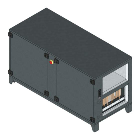
ETA K ... H
Air handling unit with heat recovery
CONTENTS
FOREWORD . . . . . . . . . . . . . . . . . . . . . . . . . . . . . . . . . . . . . . . . . . . . . . . . . . . . . . . . . . . . . . . . . . . . . . . . . . . . . . . 2
1.
IMPORTANT INFORMATION . . . . . . . . . . . . . . . . . . . . . . . . . . . . . . . . . . . . . . . . . . . . . . . . . . . . . . . . . . . . . . . . . . 2
2.
GENERAL SAFETY INSTRUCTIONS . . . . . . . . . . . . . . . . . . . . . . . . . . . . . . . . . . . . . . . . . . . . . . . . . . . . . . . . . . . . . 3
3.
ADHERE TO THE FOLLOWING INSTRUCTIONS . . . . . . . . . . . . . . . . . . . . . . . . . . . . . . . . . . . . . . . . . . . . . . . . . . . 8
4.
PRODUCT INFORMATION . . . . . . . . . . . . . . . . . . . . . . . . . . . . . . . . . . . . . . . . . . . . . . . . . . . . . . . . . . . . . . . . . . . . 8
5.
DELIVERY CONTENTS . . . . . . . . . . . . . . . . . . . . . . . . . . . . . . . . . . . . . . . . . . . . . . . . . . . . . . . . . . . . . . . . . . . . . . 10
6.
TECHNICAL DATA . . . . . . . . . . . . . . . . . . . . . . . . . . . . . . . . . . . . . . . . . . . . . . . . . . . . . . . . . . . . . . . . . . . . . . . . . . 11
7.
DIMENSIONS . . . . . . . . . . . . . . . . . . . . . . . . . . . . . . . . . . . . . . . . . . . . . . . . . . . . . . . . . . . . . . . . . . . . . . . . . . . . . 13
8.
TRANSPORT AND STORAGE . . . . . . . . . . . . . . . . . . . . . . . . . . . . . . . . . . . . . . . . . . . . . . . . . . . . . . . . . . . . . . . . . 14
9.
ASSEMBLY . . . . . . . . . . . . . . . . . . . . . . . . . . . . . . . . . . . . . . . . . . . . . . . . . . . . . . . . . . . . . . . . . . . . . . . . . . . . . . . 15
10.
ELECTRICAL CONNECTION . . . . . . . . . . . . . . . . . . . . . . . . . . . . . . . . . . . . . . . . . . . . . . . . . . . . . . . . . . . . . . . . . . 20
11.
COMMISSIONING . . . . . . . . . . . . . . . . . . . . . . . . . . . . . . . . . . . . . . . . . . . . . . . . . . . . . . . . . . . . . . . . . . . . . . . . . . 23
12.
OPERATION . . . . . . . . . . . . . . . . . . . . . . . . . . . . . . . . . . . . . . . . . . . . . . . . . . . . . . . . . . . . . . . . . . . . . . . . . . . . . . 24
13.
MAINTENANCE AND CLEANING . . . . . . . . . . . . . . . . . . . . . . . . . . . . . . . . . . . . . . . . . . . . . . . . . . . . . . . . . . . . . . 40
14.
MODBUS COMMUNICATION INTERFACE . . . . . . . . . . . . . . . . . . . . . . . . . . . . . . . . . . . . . . . . . . . . . . . . . . . . . . . 43
15.
EXPANSION AND RECONFIGURATION . . . . . . . . . . . . . . . . . . . . . . . . . . . . . . . . . . . . . . . . . . . . . . . . . . . . . . . . . 53
16.
LIFETIME AND DISPOSAL . . . . . . . . . . . . . . . . . . . . . . . . . . . . . . . . . . . . . . . . . . . . . . . . . . . . . . . . . . . . . . . . . . . 53
17.
TROUBLESHOOTING . . . . . . . . . . . . . . . . . . . . . . . . . . . . . . . . . . . . . . . . . . . . . . . . . . . . . . . . . . . . . . . . . . . . . . . 53
18.
WIRING DIAGRAM . . . . . . . . . . . . . . . . . . . . . . . . . . . . . . . . . . . . . . . . . . . . . . . . . . . . . . . . . . . . . . . . . . . . . . . . . 57
19.
+49 7930 9211-300
+49 7930 9211-166
www.ruck.eu
Example configuration shown
The original instructions were created in the
Information updated
Made in EU
2018
German language.
print 27.09.2023
Subject to change
Advertisement
Table of Contents

Related Manuals for Ruck ETA K H Series


Summary of Contents for Ruck ETA K H Series
-
Page 1: Table Of Contents
WIRING DIAGRAM . . . . . . . . . . . . . . . . . . . . . . . . . . . . . . . . . . . . . . . . . . . . . . . . . . . . . . . . . . . . . . . . . . . . . . . . . 57 ruck Ventilatoren GmbH Max-Planck-Str. -
Page 2: Foreword
The following documents and information on the device must be observed in addition to the installation, operating and maintenance instructions: Nameplate Other applicable standards: Available documents at www.ruck.eu ■ DIN VDE 0100-100 ■ Installation, operating and maintenance instructions ■ DIN EN 60204-1 ■... -
Page 3: General Safety Instructions
■ Safety components must not be bypassed or put out of operation. ■ The product may be operated by personnel with limited physical, sensory or mental capacities only if they are su- pervised or have been instructed by responsible personnel. ■ Children must be kept away from the product. www.ruck.eu |... - Page 4 3.1. Intended use Our devices are incomplete machineries as defined in the EU Machinery Directive 2006/42/EC (partly completed ma- chinery). The product is a not ready-for-use machine in terms of the machine directive. It is intended exclusively for installation in a machine or in ventilation equipment and installations or for combination with other components to form a machinery or installation.
- Page 5 » Failure to observe the hazard may lead to serious housing). injury. → Only use mild soapsuds. The impeller should be cleaned → Work may only be performed once the impeller has with a cloth or brush. come to a complete halt. www.ruck.eu |...
- Page 6 Read the operating manual Connection condensate Air filter (Panel Filter) Filter before commissioning the drainage class ISO ePM1 (F7) product. Connections for the heating Heat exchanger (Counter Air filter (Panel Filter) Filter coils cross-flow heat exchanger) class ISO ePM10 (M5) Bypass 3.5.
- Page 7 Fig. 3-3 Safety labels Direct evaporator 166346 www.ruck.eu |...
-
Page 8: Adhere To The Following Instructions
ADHERE TO THE FOLLOWING INSTRUCTIONS 4.1. General instructions ■ Persons who assemble, operate, disassemble or maintain our devices must not be under the influence of alcohol, drugs or pharmaceuticals that may affect perception and responsiveness. ■ Responsibilities for the operation, maintenance and regulation of the product should be clearly determined and observed so that there can be no unclear areas of responsibility with regard to safety. - Page 9 22. Counter cross-flow heat exchanger 23. Air filter ISO ePM1 (F7) - supply air 24. Connection intake air 25. Connection exhaust air 26. Temperature sensor fresh air 27. Temperature sensor exhaust air 28. Actuator bypass damper Fig. 5-2 www.ruck.eu |...
-
Page 10: Delivery Contents
5.2. Nameplate ATTENTION! The information on the nameplate must always be observed! Legend: UKCA marking ■ I Max. current consumption CE marking ■ t Max. ambient temperature / Max. medium temperature EAC marking ■ P Rated power consumption Product name ■... -
Page 11: Technical Data
170,0 170,0 170,0 170,0 230,0 230,0 230,0 230,0 230,0 230,0 Wiring diagrams No. 166199 166199 166199 166199 166199 166199 166200 166200 166200 166200 166200 166200 Heating coil warm water Electrical heating coil external electrical heating coil Direct evaporator www.ruck.eu |... - Page 12 Product name Item number 165421 165422 165423 165424 165425 165426 165427 165428 165429 165430 165431 165432 400V 400V 400V 400V 400V 400V 400V 400V Voltage U 230V ~ 230V ~ 230V ~ 230V ~ Frequency f Rated power consumption P 1550 1550 9050...
-
Page 13: Dimensions
600 x 400 2400 1395 ETA K 2800 H EOJL 165430 600 x 400 2400 1395 ETA K 2800 H ODJR 165431 600 x 400 2400 1395 ETA K 2800 H ODJL 165432 600 x 400 2400 1395 www.ruck.eu |... -
Page 14: Transport And Storage
8.1. Dimensions Control unit Size LxBxH 122 x 89 x 23 Assembly size Ø A Ø D 27,9 Fig. 8-2 Fig. 8-3 Outside dimensions of the control unit. Installation dimensions of the control unit. 163735 163735 TRANSPORT AND STORAGE Transport and storage should only be performed by specialist personnel in accordance with the assembly and opera- ting manual and regulations in force. -
Page 15: Assembly
Pressure losses in the duct system are adversely affected by: the length of the duct system, small duct cross-section, elbows, additional filters, valves, etc. 10.1. Permitted installation positions The units must only be mounted upright, connection nozzles horizontal. Fig. 10-1 Permitted installation positions www.ruck.eu |... - Page 16 10.2. Minimum distance for maintenance works Product name Fig. 10-2 Minimum distance for maintenance works ETA K 700 H ETA K 1300 H ETA K 2000 H ETA K 2800 H 1170 10.3. Duct connections Duct connections should be made such way that no condensate can get into the unit via the ducts. ■...
- Page 17 It is possible that the water in the pipe to the valve cools during admixture circuit. When heating is required there is a short delay before hot water gets into the heating coil. Fig. 10-6 Injection circuit The combination of these circuits is the injection circuit which is generally recommended. www.ruck.eu |...
- Page 18 10.6. Condensate drainage ■ The counter cross-flow heat exchanger is equipped with a stainless steel condensate pan. ■ A drainage connection from the condensate pan is brought out of the unit. ■ To avoid corrosion, the drain pipe from this connection should be in stainless steel, copper or plastic. ■...
- Page 19 Negative pressure at the condensate drain connection P=1500 Pa and distance A is 70 mm. R = P/10 +A = 1500/10 + 70 = 220 mm GR = R - A = 220 - 70 = 150 mm www.ruck.eu |...
-
Page 20: Electrical Connection
11. ELECTRICAL CONNECTION • Electricity warning (hazardous voltage)! » Failure to observe the hazard may result in death, injury or damage to property. → Before performing any work on conductive parts, always disconnect the unit completely from the electri- city supply and make sure that it cannot be switched back on again. The electrical installation may only be carried out by qualified electricians in compliance with the installation, operating and maintenance instructions and the applicable national regulations, standards and guidelines: ■... - Page 21 4°C after 20 minutes, the system switches off completely and the fault message F7 Frost protection appears on the control panel. The circulation pump remains switched on and the heating valve opened. If the supply air temperature rises again within 20 minutes, the device returns to normal operation. www.ruck.eu |...
- Page 22 Optional frost protection thermostat An external frost protection thermostat can be connected to the controls. As soon as the temperature drops below the set value, the dampers are closed, the fans are switched off, the circulation pump is switched on and the heating valve is opened.
-
Page 23: Commissioning
■ Correctly sealed installation of the unit and duct system. ■ Check the duct system, unit and medium lines, if present, remove any foreign bodies if necessary. ■ The intake opening and inflow into the unit must be clear. www.ruck.eu |... -
Page 24: Operation
■ Check all mechanical and electrical protection measures (e.g. earthing). ■ Voltage, frequency and type of current must correspond with the rating plate. ■ Check all electrical connections and wiring. ■ Check any electrical, switching, safety and control devices connected. ■... - Page 25 Display of the currently measured sensor values of the ventilation unit, as well as display of faults. Visible for all user levels. Status Status Actual values Room temp. Basic setting Fault SupplyAir temp. Fans Heating & Cooling ExtractAir temp. Functions ExhaustAir temp. Maintenance OutdoortAir temp. Communication System www.ruck.eu |...
- Page 26 13.1.5. Basic settings Under Settings/ Basic settings, the most important basic parameters such as unit type and minimum or maximum setpoints can be set. Can only be changed at user level „Service“ or higher. Einzelne Geräteparameter sind nur durch den Werkskundendienst einstellbar. Basic setting Status Control type...
- Page 27 Mode“ you can determine in which mode the unit starts.. Auto operation: When Auto operation mode is activated, the unit automatically switches to Standard mode if the setpoint for the sen- sor set under „Auto operation mode“ is not reached. www.ruck.eu |...
- Page 28 Night cooling: The night cooling function is intended to save energy in the summer months. By using Functions the cool air during the night hours, it is possible to cool down heated rooms. If the unit Night cooling is in standby mode and the night cooling function is activated, it switches on for a few minutes every hour between 00:00 and 05:00 to check whether the room can be pas- NightCool.temp.
- Page 29 Can only be changed at user level „Service“ or higher. Individual unit parameters can only be set by the factory customer service. System Status Authorization Service Basic setting Language Fans English Heating & Cooling Display setting Functions Time Maintenance Device name Communication System Sensor Type www.ruck.eu |...
- Page 30 13.1.12. User levels Four different user levels available (default user 3). System Authorization Authorization Service Language English Display setting Time Device name Sensor Type Save Authorization Password Explanation ■ Settings are possible only in the timer. User 1 1111 or any other number ■...
- Page 31 If time schedules are not used, a constant volume flow can be set - separately for supply and extract air. This control mode is preset for the unit in the delivery state. SupplyAir ExtractAir Setpoint temp. Enable Heating Enable Day 1 Cooling www.ruck.eu |...
- Page 32 CO2-guided air volume control CO2-guided air quality control is possible via a room or duct sensor with 0-10V output. If the measured CO2 content is below the setpoint, the unit runs with the minimum set air volume. If the measured CO2 content rises above the set- point, the air volume is increased by the control system to reduce the CO2 content in the building back to the setpoint.
- Page 33 External heat occurring in the room is compensated by correcting the supply air temperature. The temperature sensor is integrated in the remote control unit. Basic setting Control type Control type Room temp. V-Control SupplyAir temp. Control type SupplyAir temp. ExtractAir temp. Type Unit size Save www.ruck.eu |...
- Page 34 13.4. Time and schedules The time can be set and is maintained even in the event of an interruption in the input voltage. System Time Authorization Service Language English Display setting Time Time Device name Sensor Type Save Schedules with up to 6 changes of mode per day - individually for 7 days of the week. Monday Switching point Daytime timer...
- Page 35 Electric heating element (Version 700, 1300, 2000 ...E) Electric heater (Version 2800 …E) KWR*/KWRI* Cold water cooling coil DVR*/DVRI* Direct evaporator 3-way valve with actuator Temperature sensor Remote control with room temperature sensor Fire detector *Optinal depending on the type. www.ruck.eu |...
- Page 36 13.6. Functions 13.6.1. Fan error message contact Each motor has an error message contact which is closed during fan operation. The unit switches off when the contact opens. After correction of the fault (see Fault diagnosis chart), the unit can then be restarted. The fans are each controlled by a EC-controller.
- Page 37 ■ only for size 2800: in betwen airduct and EHM, an adapterplate from size 600 x 300 to size 600 x 400 should be used (not included) (1) Heating module (2) Air duct (3) Air handling unit Fig. 13-5 Connection EHM to device www.ruck.eu |...
- Page 38 Electrical connection • Electricity warning (hazardous voltage)! » Failure to observe the hazard may result in death, injury or damage to property. → Before performing any work on conductive parts, always disconnect the unit completely from the electri- city supply and make sure that it cannot be switched back on again. The electrical installation may only be carried out by qualified electricians in compliance with the installation, operating and maintenance instructions and the applicable national regulations, standards and guidelines: ■...
- Page 39 ■ Check any electrical, switching, safety and control devices connected. ■ The unit may not be switched on when the housing is open. Operation Heating module display When the heating module is correctly connected, a symbol appears in the control unit display. www.ruck.eu |...
-
Page 40: Maintenance And Cleaning
14. MAINTENANCE AND CLEANING Servicing, troubleshooting and cleaning may only be performed by specialised personnel in accordance with this installation and operating manual and the regulations in force. ■ Make sure that no connections or components are loosened unless the device is disconnected from the mains. - Page 41 Basic setting Pressure measurement FilterCal.SupplyAir1 Fans Heating & Cooling Pres.Sup.AirFilter1 Mode Standard Functions Filter ExtractAir 1 SupplyAir temp. 21.3 °C Filter change Maintenance Pressure measurement Room temp. 20.3 °C FilterCal.Extr.Air1 SupplyAir Communication ExtractAir System Air humidity Pres.Extr.AirFilter1 Save www.ruck.eu |...
- Page 42 14.3. Changing the battery Change the battery as follows: ■ Remove the control cable (1) from the control unit. ■ Open the control unit by removing the cover (2). ■ The holder (3) for the battery is on the board. Take the battery out and replace it with a new one, as shown in the image.
-
Page 43: Modbus Communication Interface
Write several device parameters word by word Function code Name Sub-function Description 08 Hex Send the received message back Return Query Dat 08 Hex Restart Communications Restart communication 08 Hex Force Listen Only Mode Switch to listen-only mode www.ruck.eu |... - Page 44 15.4. Parameter table 40101 100 Reserved integer R/W 0 - 5 (0 = Standby, 1 = Eco, 2 = Night, 3 = Stan- 40110 109 Operating mode integer R/W dard, 4 = Comfort, 5 = Party) 40111 110 Set-point temperature 1 Parameter 232 - 233 integer R/W 40112 111 Set-point temperature 2...
- Page 45 40200 199 Reserved integer R/W 40201 200 Enable Auto-Temp 1 0 - 1 0 = OFF, 1 = ON integer R/W 40202 201 Enable Auto-Temp 2 Night 0 - 1 0 = OFF, 1 = ON integer R/W www.ruck.eu |...
- Page 46 40203 202 Enable Auto-Temp 3 Standard 0 - 1 0 = OFF, 1 = ON integer R/W 40204 203 Enable Auto-Temp 4 Comfort 0 - 1 0 = OFF, 1 = ON integer R/W 40205 204 Enable Auto-Temp 5 Party 0 - 1 0 = OFF, 1 = ON integer R/W...
- Page 47 40412 411 Set 2 SP6 " integer R/W 40413 412 Set 3 SP1 " integer R/W 40414 413 Set 3 SP2 " integer R/W 40415 414 Set 3 SP3 " integer R/W 40416 415 Set 3 SP4 " integer R/W www.ruck.eu |...
- Page 48 40417 416 Set 3 SP5 " integer R/W 40418 417 Set 3 SP6 " integer R/W 40419 418 Set 4 SP1 " integer R/W 40420 419 Set 4 SP2 " integer R/W 40421 420 Set 4 SP3 " integer R/W 40422 421 Set 4 SP4 "...
- Page 49 R/W 40539 538 Set 7 Modus 3 " integer R/W 40542 539 Set 7 Modus 4 " integer R/W 40541 540 Set 7 Modus 5 " integer R/W 40542 541 Set 7 Modus 6 " integer R/W www.ruck.eu |...
- Page 50 15.5. Current value table Register Protocol Parameter name Value range Data type Authority address address 30101 Reserved integer 30111 Unit identification integer 30112 Room temperature integer 30113 Supply-air temperature integer 30114 Outlet-air temperature integer 30115 Exhaust-air temperature integer 30116 Outdoor-air temperature 1 integer 30118 Pressure difference supply air filter 1...
- Page 51 1 = Fire detector ok Reserved Bit 6 Reserved Bit 7 Reserved Bit 8 Reserved Bit 9 Bit 10 Reserved 1 = Night cooling active Bit 11 Reserved Bit 12 Reserved Bit 13 Reserved Bit 14 Reserved Bit 15 www.ruck.eu |...
- Page 52 Outputs Protocol addresses 150 Reserved Bit 0 Pump cooling Bit 1 Enable cooling device Bit 2 Bypass open Bit 3 Bypass closed Bit 4 Bit 5 Heating valve open Heating valve closed Bit 6 Pump heating Bit 7 Unit defective Bit 8 Damper closed Bit 9...
-
Page 53: Expansion And Reconfiguration
■ Connection with intake or exhaust pipe / ■ Install fan with vibration dampers duct causes vibrations / oscillations ■ Fixing screws released ■ Tighten screws ■ Fault of the ball bearings ■ Contact the supplier ■ Loose impeller blade ■ Contact the supplier www.ruck.eu |... - Page 54 Fault Possible cause Remedy methods ■ Low airflow ■ Impeller runs in the wrong direction (wrong ■ Note the marking on the device / namepla- air transport direction) te. Check electrical connections ■ High pressure losses in the system ■ Improve piping configuration or select a more powerful fan ■...
- Page 55 » Repair supply air valve, check fuses F2. » After the failure reason is remedied, the reset button of the safety thermostat has to be reset manually, and the failure has to be confirmed at the control unit with „OK“. www.ruck.eu |...
- Page 56 Error message Type of fault and repair Fault, fan thermal contact » The thermal contact has been tripped, device will be switched off. Possible cause: motor overheating or defective. (X9: 6,7,8,9) » The power supply must be switched off at the main switch for at least 20 s. Check fuse F2, replace the motor if necessary.
-
Page 57: Wiring Diagram
Vorsicherung 1 x 16A Vorsicherung 1 x 16A Fuse Fuse Hot water heating / without integrated heating: Datum 16.12.2022 ruck Ventilatoren GmbH 166199_00 Max-Planck-Strasse 5 Bearb. S. Kuhbach ETAK 700 D-97944 Boxberg Gepr. Tel +49 (0) 7930 9211-300 ETAK 700 Zustand Änderung... - Page 58 Electric heating: 58 | ETA K ... H Installation, operating and maintenance instructions...
- Page 59 Vorsicherung 1 x 16A Vorsicherung 3 x 16A Fuse Fuse Hot water heating / without integrated heating: Datum 16.12.2022 ruck Ventilatoren GmbH 166200_00 Max-Planck-Strasse 5 Bearb. S. Kuhbach ETAK 1300 D-97944 Boxberg Gepr. Tel +49 (0) 7930 9211-300 ETAK 1300 Zustand Änderung...
- Page 60 Electric heating: 60 | ETA K ... H Installation, operating and maintenance instructions...
- Page 61 Vorsicherung 1 x 16A Vorsicherung 3 x 16A Fuse Fuse Hot water heating / without integrated heating: Datum 16.12.2022 ruck Ventilatoren GmbH 166201_00 Max-Planck-Strasse 5 Bearb. S. Kuhbach ETAK 2000 D-97944 Boxberg Gepr. Tel +49 (0) 7930 9211-300 ETAK 2000 Zustand Änderung...
- Page 62 Electric heating: 62 | ETA K ... H Installation, operating and maintenance instructions...
- Page 63 400V 3~ / N / 50Hz Mains voltage Leistung 18000W Power Vorsicherung 3 x 32A Fuse Datum 16.12.2022 ruck Ventilatoren GmbH 166202_00 Max-Planck-Strasse 5 Bearb. S. Kuhbach ETAK 2800 D-97944 Boxberg Gepr. Tel +49 (0) 7930 9211-300 ETAK 2800 Zustand Änderung...
- Page 64 Electric heating: 64 | ETA K ... H Installation, operating and maintenance instructions...
- Page 65 19.5. Circuit diagram controls www.ruck.eu |...
- Page 66 0-10V 2V : min. Volumenstrom A - In A - Out <2V: Gerät Aus A - Out Datum 16.12.2022 =Drucksens ruck Ventilatoren GmbH 166199_00 +24V Max-Planck-Strasse 5 Bearb. S. Kuhbach D - In D - In D-97944 Boxberg extern Sensor / external Sensor Gepr.
- Page 67 A - In 2 3 4 5 6 7 8 9 10 11 12 13 2 3 4 5 6 7 8 9 10 11 12 13 Datum 16.12.2022 ruck Ventilatoren GmbH 166199_00 A - In Max-Planck-Strasse 5 Bearb. S. Kuhbach...
- Page 68 D - In B1: Volumenstrom Zuluft / Supply air flow D - In B2: Volumenstrom Abluft / Extract airflow Datum 16.12.2022 ruck Ventilatoren GmbH B3: Filterüberwachung Zuluft / +24V Max-Planck-Strasse 5 Bearb. S. Kuhbach Filter monitoring Supply air D - In...
-
Page 69: Ruck Ventilatoren Gmbh
Ventilatoren GmbH Max-Planck-Str. 5 D-97944 Boxberg-Windischbuch Tel. +49 7930 9211-300 +49 7930 9211-166 info@ruck.eu www.ruck.eu Information updated print 27.09.2023 mwe_khu_pb_02_k10001_en We reserve the right to make changes Language: English...
Need help?
Do you have a question about the ETA K H Series and is the answer not in the manual?
Questions and answers