
Related Manuals for Ruck ETA K 600 V W


Summary of Contents for Ruck ETA K 600 V W
- Page 1 137368 Assem b l y an d Op erati n g M an u a l Air handling unit with heat recovery ETA K 600 V W ETA K 600 V E ETA K 1200 V W English ETA K 1200 V E...
- Page 2 This document, as well as the data, specifications and other in- formation set forth in it, are the exclusive property of ruck Ven- tilatoren GmbH. It may not be reproduced or given to third parties without its con- sent.
-
Page 3: Table Of Contents
9.6.1. Time / Time switch ................ 31 9.7. Functions ..................33 9.7.1 Fan error message contact ............33 9.7.2 Hot water coil / frost protection ............. 33 9.7.3 Safety temperature limiter for types with electrical heating coil ... 34 www.ruck.eu... - Page 4 English 10. Maintenance and repair ................ 37 10.1. Important notes ................37 10.2. Cleaning and care ................ 37 10.3. Maintenance ................. 38 10.3.1. Counter cross-flow heat exchanger ..........38 10.3.2. Air filters ..................38 10.3.3. Changing the battery ..............39 11.
-
Page 5: Important Information
1.2. Guarantee and liability ruck ventilation devices are produced on the highest technical level according to the generally ac- cepted rules of technology. They are subject to constant quality control and meet the relevant requi- rements when delivered. Because the products are being constantly developed, we reserve the right to make changes to the products at any time and without prior announcement. -
Page 6: Improper Use
English 2.2. Improper use Any use of the product other than described in chapter “Intended use” is considered as improper. The following points are improper and dangerous: Delivery of explosive and flammable media or operation in potentially explosive atmospheres. • Delivery of aggressive and abrasive media. -
Page 7: Adhere To The Following Instructions
Observe the provisions for accident prevention and environmental protection for the country • where the product is used and at the workplace. Persons who assemble, operate, disassemble or maintain ruck products must not consu- • me any alcohol, drugs or pharmaceuticals that may affect their ability to respond. -
Page 8: Safety Labels On The Product
English 2.6. Safety labels on the product ETA K 600 V Heater 139235 ETA K 600 V Electrical heating coil 139234 Tel. +49 7930 9211-0 Fax +49 7930 9211-150... - Page 9 English ETA K 1200 V Heater 139237 ETA K 1200 V Electrical heating coil 139236 www.ruck.eu...
-
Page 10: Delivery Contents
English • General warning • Electricity warning (hazardous voltage)! » Failure to observe the warnings may result in personal » Failure to observe the hazard may result in death, injury or injury and / or damage to property. damage to property. →... -
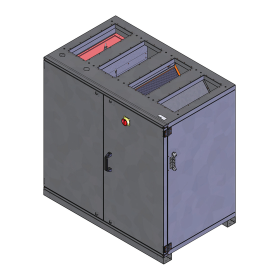
Page 11: Device Description
26. Temperature sensor fresh air 8. Connection heating coil 17. Safety labels 27. Temperature sensor exhaust air 9. Connection supply air 18. Switchboard cover 10. Connection extract air 19. Actuator bypass damper Fig. 2: ETA K 1200 V 36 www.ruck.eu 137371... -
Page 12: Transport And Storage
English Transport and storage Transport and storage should only be performed by specialist personnel in accordance with the assembly and operating manual and regulations in force. The following points should be noted and followed: Check the delivery according to the delivery note to ensure it is complete and correct and check for •... -
Page 13: Permitted Installation Positions
It is possible that the water in the pipe to the valve cools during admixture circuit. When heating is required there is a short delay before hot water gets into the heating coil. Injection circuit Fig. 8: The combination of these circuits is the injection circuit which is generally recommended. Injection circuit www.ruck.eu... -
Page 14: Condensate Drainage
English 6.5. Condensate drainage The counter cross-flow heat exchanger is equipped with a stainless steel condensate pan. • A drainage connection from the condensate pan is brought out of the unit. • To avoid corrosion, the drain pipe from this connection should be in stainless steel, copper or •... -
Page 15: Electrical Connection
The extra-low voltage control cables must be laid separately from the mains cables. Fig. 12: Fig. 13: Connection compartment Cable glands 137371 (1) Controller board (3) Cable gland power supply 137371 (2) Switchboard cover (4) Cable gland free (5) Cable gland control unit B (1 : 9) www.ruck.eu... -
Page 16: Overcurrent Protection
Modbus. Multiple devices can be connected to the bus with an adapter board as accessory. The unit can be visualized using the ruck view software software. All parameters, measured and set values can be controlled with ruck view. -
Page 17: Commissioning
• The intake opening and inflow into the unit must be clear. • Check all mechanical and electrical protection measures (e.g. earthing). • Voltage, frequency and type of current must correspond with the rating plate. • Check all electrical connections and wiring. www.ruck.eu... -
Page 18: Operation
English • Check any electrical, switching, safety and control devices connected. • The unit may not be switched on when the housing is open. • Measure electricity consumption at operating speed and compare with the rated current. • Check the fan for excessive vibrations and noise generation. Operation 9.1. -
Page 19: Adjustment Of The Control Unit Parameter
The display switches into operating mode. Depending on the application, the devices are delivered with language selection 1 or 2. DEUTSCH ENGLISH FRANCAIS DANSK ESPAÑOL NEDERLANDS PORTUGUÊS POLSKI SLOVENCINA ROMANA Русский TURKISH SLOVENSCINA HRVATSKI MAGYAR MONGOLOOR 2 sec SUOMI www.ruck.eu... -
Page 20: Overview Menu Management
English 9.2. Overview menu management Tel. +49 7930 9211-0 Fax +49 7930 9211-150... - Page 21 English www.ruck.eu...
- Page 22 English Tel. +49 7930 9211-0 Fax +49 7930 9211-150...
-
Page 23: Display User Level
The selection is made from right to left. MOTION DETECTOR FIRE PROTECTION 1 = OK unimplemented UNUSED Description: unimplemented UNUSED 0 = false unimplemented UNUSED unimplemented UNUSED 1 = true unimplemented UNUSED unimplemented UNUSED unimplemented UNUSED unimplemented UNUSED unimplemented UNUSED unimplemented UNUSED www.ruck.eu... -
Page 24: Commissioning Level (Trained Personnel)
English Hours of operation OPERATING HOURS The current number of hours for which the unit has been in constant operation. 1 x 10 Value x 10 in hours. • Filter change counter FILTER CHANGE Number of filter changes made. The value rises automatically whenever a filter has been correctly changed. - Page 25 SHOCK VENT The air handling unit runs on closing the external contact to the motion sensor and in Level 3 at the Factory setting volume flows set in P19 and P28. 600 m³/h SHOCK VENT Factory setting Continued on page www.ruck.eu...
- Page 26 English ETAK-P: Constant pressure control Constant 6 sec hold down P 13 ETAK-P Constant pressure control Operating mode P is the common control mode for the operation with variable air vo- Factory setting lumes by variable air volume controllers. The desired supply and extract air pressure P13 TYP can be set with the control unit.
- Page 27 The duct pressure required for „BASIC VENTILATION“ can be set on the control unit in Pa. The 250 PA extract air volume automatically follows up the supply air volume. Complex adjustments are thus not BASIC VENT necessary and the air volume for the building ventilation can be adjusted exactly. Continued on page www.ruck.eu...
- Page 28 English The following parameters for all 3 control modes: P 21 Room, supply or extract air temperature regulation The room, supply air or extract air temperature regulator compares the air temperature measured at the temperature sensors with the reference temperature set on the control unit In the case of he- ating, a difference between the set-point and actual temperature causes the controller to increase ROOMTEMP.CONTROL or reduce the heat output.
-
Page 29: Menu Parameter Level
The unit can only be switched on if the contact is closed. If the contact is open, the P3 ENABLE display will show „NOT ENABLE“. The contact should be closed and then acknow- ACKNOWLEDGED ledged with button B (▲). The default mode is AUTOMATIC. www.ruck.eu... -
Page 30: Menu Functions
English P 4 I - component P4 I-COMPONENT A value between 5-20 can be set for the I – component. The factory setting is at 10. If the value decreases, the control becomes more sensitive. CAUTION! Due to highly sensitive settings, the control tends to pulsate. ... -
Page 31: Time / Time Switch
The values set are saved even when there is a power failure or if the battery in the control unit runs 4:30 ON down. Only the current time and day of the week have to be reset. 22:30 OFF Note: Instructions on changing the clock battery are give in section 10.3.3. www.ruck.eu... - Page 32 English Setting day - night switch-over This menu has the same functions as the timer. The only difference is that the device is not switched on (ON) or off (OFF), but from day to night mode. The device runs in day mode with the basic ventilation volume flow. The device runs in night mode with the minimum ventilation volume flow.
-
Page 33: Functions
The unit restarts then automatically. If the desired operating temperature cannot be achieved after 20 min., an error message is displayed. Afterwards, the unit turns itself completely off until the fault is repaired. (see 14.2. Error table F07) www.ruck.eu... -
Page 34: Safety Temperature Limiter For Types With Electrical Heating Coil
English 9.7.3 Safety temperature limiter for types with electrical heating coil Electricity warning (hazardous voltage)! • Failure to observe the hazard may result in death, injury or damage to property. » Before performing any work on conductive parts, always disconnect the unit completely →... - Page 35 First use the control cable (1) supplied with the heating module to connect the air handling unit (4) to the heating module (3). Connect the surplus control cable (2) from the air handling unit to the second RJ10 socket on the control board of the heater module (3). Then connect the other end of the control www.ruck.eu...
- Page 36 English cable directly from below to the RJ10 socket on the control unit. The control cable must not be shor- tened. Any excess length must be stowed outside of the housing. If the cable is too short, extensions can be ordered from the manufacturer or supplier. Fig.
-
Page 37: Maintenance And Repair
Servicing, troubleshooting and cleaning may only be performed by specialised personnel in accordance with this installation and operating manual and the regulations in force. If operated correctly, ruck products only require a small amount of maintenance. The following work should be performed at regular intervals, in accordance with health and safety regulations: Check the operation of the control system and safety devices. -
Page 38: Maintenance
English 10.3. Maintenance 10.3.1. Counter cross-flow heat exchanger Counter cross-flow heat exchangers generally require no maintenance. For hygienic reasons, clea- ning of the exchanger is occasionally recommended. Damage to the blades should always be avo- ided. Use warm, flowing water for cleaning. Door Counter cross-flow heat exchanger Fig. -
Page 39: Changing The Battery
You only have to reset the current time (see Section 9.4.). The battery symbol disappears from • the status display. Your control unit is fully functional again. Note: requires a 3 V lithium CR 1616 button cell battery. Fig. 25 125987 (1) Control cable (2) Control unit cover 125987 (3) Battery holder www.ruck.eu... -
Page 40: Modbus Communication Interface
English 11. Modbus communication interface 11.1. Wiring diagram Place Jumper K 1 for the last device on the bus Signal line B with 10 kOhm to GND Signal line A with 10 kOhm to +24 V Control unit 120 Ohm Line Line Fig. -
Page 41: Parameter Table
1 = Minimum ventilation 2 = Basic ventilation 40033 Ventilation change-over integer 3 = Intermittent ventilation 40034 Status and control word See Table below integer 40035 integer Reserved 40036 Save parameters 12439 Value change after saving under 0 integer www.ruck.eu... - Page 42 English Register Parameter name Value range address ETA K 600 ETA K 1200 ETA K 2400 40016 Minimum ventilation supply air 200 - 740 m³/h 400 - 1370 m³/h 40017 Minimum ventilation extract air 200 - 740 m³/h 400 - 1370 m³/h 40018 Basic ventilation supply air 200 - 740 m³/h...
-
Page 43: Current Value Table
0-2000 ppm / 0-100 % Humidity integer See Table below 30025 Error number integer 30026 Reserved integer 30027 Pressure supply air analogue input 2 integer 30028 Pressure extract air analogue input 3 integer 30029 Reserved integer 30030 Reserved integer www.ruck.eu... - Page 44 English Current value table, protocol addresses 13 (inputs) Bit 0 1 = Enable_signal_external Bit 1 1 = Frequency converter ready Fan motor electronic ok Bit 2 1 = Thermal switch, fan Bit 3 1 = Frost protection OK Bit 4 1 = Motion detector Bit 5 1 = Fire detector ok...
-
Page 45: Expansion And Reconfiguration
If you have not been able to remove the fault, please contact the manufacturer. The contact address can be found at www.ruck.eu or on the back cover of this assembly and operating manual. 14.1. Low-current fuses There are two low-current fuses built-in at the controller circuit board to protect the electrical equip- ment. -
Page 46: Fault Diagnosis Chart
English 14.2. Fault diagnosis chart If a fault occurs on the unit, one or more fault messages will appear on the display. A fault is ack- nowledged with button B (▲). It is not possible to use the control unit until all of the faults have been removed and acknowledged. -
Page 47: Technical Data
Dimensions of the supply air unit ETA K...V Ø B Ø D Fig. 28a: Fig. 28: Installation dimensions Outside dimensions of the 125987 of the control unit. control unit. Control unit Size 82+82+30 B+H+T Assembly size Ø B Ø D www.ruck.eu... -
Page 48: Appendix
English 16. Appendix 16.1. List of parameters The following table lists all of the parameters that are displayed on the control unit, some of which may be changed. Section 9.3.4. „Parameter settings menu“ gives full instructions on operating and setting the corresponding parameters. Consequence Range of values Factory setting... -
Page 49: Technical Drawings
English 16.2. Technical drawings ETA K 600 V 1060 Zuluft / Supply Air Abluft / Extract Air Aussenluft / Fresh Air Fortluft / Exhaust Air www.ruck.eu... - Page 50 English ETA K 1200 V 1395 1303 Zuluft / Supply Air Abluft / Extract Air Aussenluft / Fresh Air Fortluft / Exhaust Air Tel. +49 7930 9211-0 Fax +49 7930 9211-150...
-
Page 51: Wiring Diagram
1 x 16A Fuse ye / 8 bu / 6 ye / 9 bu / 7 Datum 14.11.2016 137793_00 ruck Ventilatoren GmbH Max-Planck-Strasse 5 Bearb. S. Kuhbach ETAK 600 D-97944 Boxberg Gepr. ETAK 600 Tel +49 (0) 7930 9211-300 Zustand Änderung... - Page 52 English ETA K 600 Wiring diagram No.: 137793 Part 2 ye / 8 bu / 6 ye / 9 bu / 7 1.50 mm² A - Out A - Out D - In +24V Tel. +49 7930 9211-0 Fax +49 7930 9211-150...
- Page 53 English ETA K 600 Wiring diagram No.: 137793 Part 3 A - Out A - Out D - In +24V www.ruck.eu...
- Page 54 3 x 16A Fuse ye / 8 bk / 6 ye / 9 bk / 7 137794_00 Datum 03.11.2016 ruck Ventilatoren GmbH Max-Planck-Strasse 5 Bearb. S. Kuhbach ETAK 1200 D-97944 Boxberg Gepr. Tel +49 (0) 7930 9211-300 ETAK 1200 Zustand Änderung...
- Page 55 English ETA K 1200 Wiring diagram No.: 137794 Part 2 ye / 8 bk / 6 ye / 9 bk / 7 1.50 mm² A - Out A - Out D - In +24V www.ruck.eu...
- Page 56 English ETA K 1200 Wiring diagram No.: 137794 Part 3 A - Out A - Out D - In +24V Tel. +49 7930 9211-0 Fax +49 7930 9211-150...
- Page 57 A - In 2V : min. Volumenstrom A - Out A - Out <2V: Gerät Aus +24V Datum 03.11.2016 =Drucksensor ruck Ventilatoren GmbH 137794_00 D - In Max-Planck-Strasse 5 Bearb. S. Kuhbach D-97944 Boxberg extern Sensor / external Sensor Gepr.
- Page 58 Temp 2 Temp 3 -X16 Temp 4 +24V L1 L11 L2 L21 L3 L31 N N N PE PE PE PE Datum 03.11.2016 ruck Ventilatoren GmbH 1377 Max-Planck-Strasse 5 Bearb. S. Kuhbach D-97944 Boxberg extern Sensor / external Sensor Gepr.
- Page 59 English Notes: www.ruck.eu...
- Page 60 This document, as well as the data, specifica- tions and other information set forth in it, are the exclusive property of ruck Ventilatoren GmbH. It may not be reproduced or given to third parties without its consent.
Need help?
Do you have a question about the ETA K 600 V W and is the answer not in the manual?
Questions and answers