
Related Manuals for Ruck ETA K 2400 V W


Summary of Contents for Ruck ETA K 2400 V W
- Page 1 Assem b l y an d Op erati n g M an u a l Air handling unit with heat recovery ETA K 600 V W ETA K 600 V E ETA K 1200 V W English ETA K 1200 V E ETA K 2400 V W ETA K 2400 V E www.ruck.eu...
- Page 2 This document, as well as the data, specifications and other in- formation set forth in it, are the exclusive property of ruck Ven- tilatoren GmbH. It may not be reproduced or given to third parties without its con- sent.
-
Page 3: Table Of Contents
9.7.1. Control type ETA K-S: Constant volume flow control ....24 9.7.2. Control type ETA K-P: Constant pressure control ......30 9.7.3. Control type ETA K-PV: Constant pressure control with balanced air volume ..................31 9.8. Menu level Commissionning ETA K ..........34 www.ruck.eu... - Page 4 English 9.9. Time / Time switch ................ 36 9.9.1. Setting the current time / day ............36 9.9.2. Setting the timer ................37 9.9.2.1. Timer on and off switching ............37 9.9.3. Setting day - night switch-over ............. 38 9.9.4. System drawings ................39 9.10.
-
Page 5: Important Information
1.2. Guarantee and liability ruck ventilation devices are produced on the highest technical level according to the generally ac- cepted rules of technology. They are subject to constant quality control and meet the relevant requi- rements when delivered. Because the products are being constantly developed, we reserve the right to make changes to the products at any time and without prior announcement. -
Page 6: Improper Use
English 2.2. Improper use Any use of the product other than described in chapter “Intended use” is considered as improper. The following points are improper and dangerous: Delivery of explosive and flammable media or operation in potentially explosive atmospheres. • Delivery of aggressive and abrasive media. -
Page 7: Adhere To The Following Instructions
Observe the provisions for accident prevention and environmental protection for the country • where the product is used and at the workplace. Persons who assemble, operate, disassemble or maintain ruck products must not consu- • me any alcohol, drugs or pharmaceuticals that may affect their ability to respond. -
Page 8: Safety Labels On The Product
English 2.6. Safety labels on the product ETA K 600 V Heater 138086 138086 139235 ETA K 600 V Electrical heating coil 138086 138086 139234 Tel. +49 7930 9211-0 Fax +49 7930 9211-150... - Page 9 English ETA K 1200 V Heater 137368 139237 ETA K 1200 V Electrical heating coil 137368 139236 www.ruck.eu...
- Page 10 English ETA K 2400 V Heater 139596 ETA K 2400 V + external electrical heating coil 139597 Tel. +49 7930 9211-0 Fax +49 7930 9211-150...
-
Page 11: Delivery Contents
Extractable large panel filters M5 / F7. • Controller installed, wired, ready to plug in. • Main / Isolator switch • External control unit with control cable. • Protection class: in ceiling installation correct duct and cable connection, IPX4 (see 6.1. Permitted • installation positions). www.ruck.eu... -
Page 12: Device Description
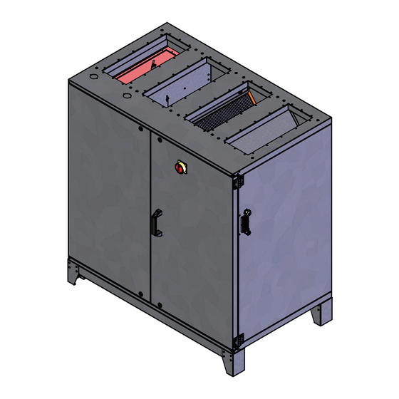
English 4.1. Device description ETA K...V Fig. 1 ETA K 1200 V TeileId Legend 137368 1. Housing 11. Connection condensate drainage 20. Extracted air temperature sensor 2. Door 12. Remote control 21. Air filter M5 - extract air 3. Isolator switch 13. -
Page 13: Transport And Storage
2/3 the unit‘s maximum pressure so that an adequate air output can still be achieved. This will prevent malfunction. Pressure losses in the duct system are adversely affected by: the length of the duct system, small duct cross-section, elbows, additional filters, valves, etc. www.ruck.eu... -
Page 14: Permitted Installation Positions
English 6.1. Permitted installation positions Exclusive mounting in upright position, connection nozzles upwards. (Fig. 4) 6.2. Duct connections Duct connections should be made such way that no condensate can get into the unit via the ducts. Insulate cold ducts in warm rooms •... -
Page 15: Condensate Drainage
5. Pipe D = 40 with union nut 1 1/2“, L = 450 mm 6. Gasket 1 1/2“ (flat) 7. Back-pressure valve 8. Round rubber gasket D = 48 9. Screw cap 1 1/2“ 10. Back-pressure ball 11. Screw cap 2“ www.ruck.eu... -
Page 16: Electrical Connection
English Electrical connection Electricity warning (hazardous voltage)! • Failure to observe the hazard may result in death, injury or damage to property. » Before performing any work on conductive parts, always disconnect the unit completely → from the electricity supply and make sure that it cannot be switched back on again. Electrical installation may only be performed by qualified electricians in accordance with the installation and operating manual and the national regulations, standards and guidelines in force: EN, DIN and VDE specifications, including all safety requirements. -
Page 17: Overcurrent Protection
Modbus. Multiple devices can be connected to the bus with an adapter board as accessory. The unit can be visualized using the ruck view software software. All parameters, measured and set values can be controlled with ruck view. -
Page 18: Commissioning
English Frost protection via supply air sensor If the supply air temperature drops below 4°C, the unit goes into the preheating mode. The dampers are closed, the fans are switched off, the circulation pump is switched on and the heating valve is opened. -
Page 19: Control Unit General
OFF unit ON 21,0°C SELECTION MENU 9:51 Display user level Commissioning level (qualified personnel) Selection Operating parameters Selection Commissioning parameters Selection Actual values Selection Timer ON/OFF Selection Timer DAY/NIGHT Selection Setting actual time Selection Timer activation Selection Language Selection OK www.ruck.eu... -
Page 20: Changing Setpoint Temperature And Fan Steps
English 9.3. Changing setpoint temperature and fan steps Switching the unit on/off on the control unit. 10:44 By selecting „ON/OFF“, the unit is switched on or off The unit‘s status now appears on the display with the current values. » Set-point temperature display »... -
Page 21: Adjustment Of The Control Unit Parameter
13 HRVATSKI Croatian 5 NEDERLANDES Dutch 14 MAGYAR Hungarian 6 PORTUGUES Portuguese 15 MONGOLOOR Mongolian 7 POLSKI Polish 16 SUOMI Finnish 8 SLOVENCINA Slovakian By selecting „OK“, you confirm the chosen language. 9:51 The display switches into operating display. www.ruck.eu... -
Page 22: Display User Level Eta K
English 9.6. Display user level ETA K You access the menu of the user level by touching the „Settings“ icon. The selection menu will then 9:51 appear on the display. 21,0°C Selection menu 9:51 You can see the actual values by touching the „Actual values“ icon. Actual values Display only, no changes are possible. - Page 23 The current number of hours for which the unit has been in constant operation. • Value x 10 in hours. 0 X 10 Filter change counter 9:51 FILTER CHANGE Number of filter changes made. The value rises automatically whenever a filter has been correctly changed. 9:51 21,0°C www.ruck.eu...
-
Page 24: Menu Level Operating Parameters (Qualified Personnel) Eta K
English 9.7. Menu level Operating parameters (qualified personnel) ETA K 9:51 You can access the Commissioning level by selecting the „Settings“ icon. The display then shows 21,0°C the selection menu. Selection menu 9:51 Now you can access the Operating parameters by touching the „Operating parameters“ icon. It is necessary to provide a password. This will remain valid for 30 min. After 30 minutes it is neces- 9:51 sary to retype the password in order to continue making changes. - Page 25 The air handling unit runs on closing the external contact to the motion sensor and in Level 3 at the SUPPLY AIR volume flows set in P19 and P28. SHOCK VENT 1200 m³/h 9:51 EXTRACT AIR SHOCK VENT 1200 m³/h Continued on page 32! www.ruck.eu...
- Page 26 English Sensor type -CO2- P 14 Sensor type CO2 9:51 Volumetric flow, demand controlled by CO2 of the extract air SENSORTYPE W/O EXT.SENSOR 9:51 SENSORTYPE W/O EXT.SENSOR Factory setting 9:51 9:51 SENSORTYPE SENSORTYPE P 23 and P 24 9:51 These settings can be found in the measuring range of the used measuring transducer. The measu- EXT.SENSOR ring range is already preset for devices with integrated CO2 sensor.
- Page 27 When using external measuring transducers, the maximum air flow rate can be adjusted by para- AIR QUALITY meter P 20. Example: 1400 PPM Class room CO²: Measuring area sensor 0 - 5000 ppm VOC: Measuring area sensor 0 - 5000 ppm Continued on page 32! www.ruck.eu...
- Page 28 English Sensor type -HUMIDITY- P 14 Sensor type humidity 9:51 Volumetric flow, demand controlled by external measuring transducer (humidity) SENSORTYPE W/O EXT.SENSOR 9:51 SENSORTYPE W/O EXT.SENSOR Factory setting 9:51 SENSORTYPE 9:51 SENSORTYPE 9:51 9:51 SENSORTYPE SENSORTYPE HUMIDITY HUMIDITY P 23 and P 24 9:51 These settings can be found in the measuring range of the used measuring transducer.
- Page 29 External volume flow control via 0 - 10 V input (see wiring diagram). SENSORTYPE W/O EXT.SENSOR 9:51 SENSORTYPE W/O EXT.SENSOR Factory setting 9:51 SENSORTYPE 9:51 SENSORTYPE 9:51 SENSORTYPE HUMIDITY 9:51 9:51 SENSORTYPE SENSORTYPE EXT.CTRL. EXT.CTRL. Continued on page 32! www.ruck.eu...
-
Page 30: Control Type Eta K-P: Constant Pressure Control
English 9.7.2. Control type ETA K-P: Constant pressure control P 13 ETA K-P Constant pressure control 9:51 Operating mode P is the common control mode for the operation with variable air volumes by variable air volume controllers. The desired supply and extract air pressure can be set with the control unit. Two pressure sensors SEN P are necessary for this operating mode. -
Page 31: Control Type Eta K-Pv: Constant Pressure Control With Balanced Air Volume
SUPPLY AIR tract air volume automatically follows up the supply air volume. Expensive control methods can thus BASIC VENT be omitted and the air volume balance for the building ventilation can be automatically implemented. 180 PA Continued on page 32! www.ruck.eu... - Page 32 English The following parameters are for all types of control: P 21 Room, supply or extract air temperature regulation 9:51 The room, supply air or extract air temperature regulator compares the air temperature measured at the temperature sensors with the reference temperature set on the control unit In the case of heating, a difference between the set-point and actual temperature SUP.AIR TEMP.CON causes the controller to increase or reduce the heat output.
- Page 33 P 30 Follow-up time 9:51 This parameter sets the stop delay of the motion detector input. The device runs for inter- RUN-ON TIME mittent ventilation with the adjusted time according to parameter 19 and 28. 5 MIN. 9:51 21,0°C www.ruck.eu...
-
Page 34: Menu Level Commissionning Eta K
English 9.8. Menu level Commissionning ETA K 9:51 You can access the parameter settings by selecting the „Settings“ icon. The selection menu will then 21,0°C appear on the display. Selection menu 9:51 Next you enter the Commissioning level by selecting the icon „Commissioning parameters“. It is necessary to provide a password. - Page 35 2400, 4800, 9600, 14400 and 19200 baud rates can be set. 1 stop bit (fixed), no parity 9600 P 9 Fan calibration supply air 9:51 FAN BALANCE SUPPLY AIR 0,960 P 10 Fan calibration extract air 9:51 FAN BALANCE EXTRACT AIR 0,930 9:51 21,0°C www.ruck.eu...
-
Page 36: Time / Time Switch
English EXTRACT FRESH AIR WWR/EHR KWR/DVR/ KWRI/DVRI* SUPPLY EXHAUST AIR Control M1 - M2* Flap system drive Fig. 15: V1 - V2 EC-fan Connection diagram ETA K...V M5/ F7 Air filter (Class M5/F7) Heat exchanger Bypass Actuators Damper system Warm water heating coil (Version …W) Electric heating element (Version 600,1200…E) Electric heater (Version 2400 …E) KWR*/KWRI*... -
Page 37: Setting The Timer
You can switch from the Operating display to the Selection menu through the „Settings“ icon. By 21,0°C selecting the „Timer“ icon, the timer cand be switched on or off. When the timer is on, a continuous clock symbol is shown on the display. 10:41 10:41 10:41 Timer on Timer off www.ruck.eu... -
Page 38: Setting Day - Night Switch-Over
English 9.9.3. Setting day - night switch-over This menu has the same functions as the timer. The only difference is that the device is not switched 10:45 on (ON) or off (OFF), but from day to night mode. The device runs in day mode with the basic ventilation volume flow. 21,0°C The device runs in night mode with the minimum ventilation volume flow. -
Page 39: System Drawings
Basic ventilation 4:00 22:00 Day 1 Fig. 18: 10:44 10:45 Systematic drawing for timer and day- night switch-over settings DAY 1 21,0°C 18:00 22:00 0:00 0:00 0:00 0:00 Basic ventilation Minimum ventilation 18:00 22:00 4:00 Day 1 www.ruck.eu... -
Page 40: Functions
English 9.10. Functions 9.10.1 Fan error message contact Each motor has an error message contact which is closed during fan operation. The unit switches off when the contact opens. After correction of the fault (see 14.2. Fault diagnosis chart), the unit can then be restarted. -
Page 41: For Version With Electric Heating Module (Ehm)
The heating module must maintain a minimum • distance (L) of between 0.50m and 4.00m from the air handling unit. 1. Heating module 2. Air duct 3. ETA K 2400 VE Fig. 21: 139268 Connection EHM to ETA K 2400 VE 139268 www.ruck.eu... - Page 42 English Electrical connection Electricity warning (hazardous voltage)! • Failure to observe the hazard may result in death, injury or damage to property. » Before performing any work on conductive parts, always disconnect the unit completely → from the electricity supply and make sure that it cannot be switched back on again. Electrical installation may only be performed by qualified electricians in accordance with the installa- tion and operating manual and the national regulations, standards and guidelines in force: EN, DIN and VDE specifications, including all safety requirements.
- Page 43 Check any electrical, switching, safety and control devices connected. • The unit may not be switched on when the housing is open. • Operation 15:10 21,0°C Heating module display When the heating module is correctly connected, a symbol ap- pears in the control unit display. www.ruck.eu...
-
Page 44: Maintenance And Repair
Servicing, troubleshooting and cleaning may only be performed by specialised personnel in accordance with this installation and operating manual and the regulations in force. If operated correctly, ruck products only require a small amount of maintenance. The following work should be performed at regular intervals, in accordance with health and safety regulations: Check the operation of the control system and safety devices. -
Page 45: Maintenance
When changing the filter, make sure that the filter frame is sitting correctly on the guide rail in the • device. Then the filter display must be reset and the new air filter calibrated. • Fig. 24: Position air filter 137368 www.ruck.eu... -
Page 46: Changing The Battery
English Calibrate filter Status display: 9:51 The differential pressure increases as one of the air filters becomes more clogged. When the pres- 100% 100% sure reaches the value set on the corresponding pressure sensor, this can be seen on the status 21,0°C display. -
Page 47: Modbus Communication Interface
Write several device parameters word by word Function Name Sub-function Description code 08 Hex Return Query Dat Send the received message back 08 Hex Restart Communications 01 Restart communication 08 Hex Force Listen Only Mode Switch to listen-only mode www.ruck.eu... -
Page 48: Parameter Table
English 11.4. Parameter table Register Protocol Parameter name Value range Data type Authority address address 40001 Reserved integer 100 - 200 corresponds to 10.0 - 20.0 °C 40002 Minimum target temperature integer 40003 Maximum target temperature 200 - 350 corresponds to 20.0 - 35.0 °C integer 0 = Automatic start 40004... - Page 49 1 = present 0 = not present Bit 8 E-heating module 1 1 = present 0 = not present Bit 9 E-heating module 2 Bit 10 Reserved Bit 11 Reserved Bit 12 Reserved Bit 13 Reserved Bit 14 Reserved Bit 15 Reserved www.ruck.eu...
-
Page 50: Current Value Table
English 11.5. Current value table Register Protocol Parameter name Value range Data type Authority address address 30001 Unit identification 10000 integer 30002 Room temperature Temp in 1/10 ° - 500 to 1000 integer 30003 Supply-air temperature Temp in 1/10 ° - 500 to 1000 integer Temp in 1/10 °... - Page 51 Outdoor-air temperature sensor defective Damper position Frost protection triggered Safety thermostat triggered Thermal switch for ventilator triggered Fan defective Reserved Not enabled Cooling plant defective Fire detector Reserved Reserved Supply-air temperature too low Supply-air temperature too hot Reserved Heat exchanger www.ruck.eu...
-
Page 52: Expansion And Reconfiguration
If you have not been able to remove the fault, please contact the manufacturer. The contact address can be found at www.ruck.eu or on the back cover of this assembly and operating manual. 14.1. Low-current fuses There are two low-current fuses built-in at the controller circuit board to protect the electrical equip- ment. -
Page 53: Fault Diagnosis Chart
» The outside air temperature sensor is defective or the cable is broken. » Replace the defective temperature sensor or replace the broken cable if necessary. » After the failure reason is remedied, the failure must be confirmed with „OK“. www.ruck.eu... - Page 54 English Faults displayed Type of fault and repair FROST PROTEC 10:12 FAULT Error frost protection » The air temperature has fallen below the value set on the antifreeze thermostat. The fans will be switched off, the air flaps closed, the heating valve fully opened and the circulating pump switched on. »...
-
Page 55: Technical Data
Fig. 27: Dimensions of the supply air unit ETA K...V 137368 Fig. 28a: Fig. 28: Installation dimensions Outside dimensions of the of the control unit. control unit. TeileId Control unit Size 82+82+30 B+H+T Assembly size Ø B Ø D www.ruck.eu... -
Page 56: Appendix
English 16. Appendix 16.1. List of parameters The following table lists all of the parameters that are displayed on the control unit, some of which may be changed. Section 9.3.4. „Parameter settings menu“ gives full instructions on operating and setting the corresponding parameters. Consequence Range of values Factory setting... -
Page 57: Technical Drawings
English 16.2. Technical drawings ETA K 600 V 1060 Zuluft / Supply Air Abluft / Extract Air Aussenluft / Fresh Air Fortluft / Exhaust Air www.ruck.eu... - Page 58 English ETA K 1200 V 1395 1303 Zuluft / Supply Air Abluft / Extract Air Aussenluft / Fresh Air Fortluft / Exhaust Air Tel. +49 7930 9211-0 Fax +49 7930 9211-150...
- Page 59 English ETA K 2400 V 1842 1750 1750 Zuluft / Supply Air Abluft / Extract Air Aussenluft / Fresh Air Fortluft / Exhaust Air www.ruck.eu...
-
Page 60: Wiring Diagram
Leistung 3350W Power Power Vorsicherung 1 x 16A Vorsicherung 1 x 16A Fuse Fuse Datum 14.11.2016 ruck Ventilatoren GmbH 137793_00 Max-Planck-Strasse 5 Bearb. S. Kuhbach ETAK 600 D-97944 Boxberg Gepr. Tel +49 (0) 7930 9211-300 ETAK 600 Zustand Änderung Datum... - Page 61 English ETA K 600 Wiring diagram No.: 137793 Part 2 1.50 mm² 1.50 mm² A - Out GNYE A - Out 1.50 mm² D - In +24V www.ruck.eu...
- Page 62 English ETA K 600 Wiring diagram No.: 137793 Part 3 A - Out A - Out D - In +24V Tel. +49 7930 9211-0 Fax +49 7930 9211-150...
- Page 63 Power Power Vorsicherung 1 x 16A Vorsicherung 3 x 16A Fuse Fuse Datum 03.11.2016 137794_00 =ETAK ruck Ventilatoren GmbH Max-Planck-Strasse 5 Bearb. S. Kuhbach ETAK 1200 D-97944 Boxberg Gepr. Tel +49 (0) 7930 9211-300 ETAK 1200 Zustand Änderung Datum Name Norm Ursp.
- Page 64 English ETA K 1200 Wiring diagram No.: 137794 Part 2 1.50 mm² A - Out A - Out D - In +24V 1.50 mm² GNYE 1.50 mm² Tel. +49 7930 9211-0 Fax +49 7930 9211-150...
- Page 65 English ETA K 1200 Wiring diagram No.: 137794 Part 3 A - Out A - Out D - In +24V www.ruck.eu...
- Page 66 18000W Leistung 18000W Power Power Vorsicherung 3 x 32A Vorsicherung 3 x 32A Fuse Fuse Datum 21.03.2017 ruck Ventilatoren GmbH 137796_00 =ETA Max-Planck-Strasse 5 Bearb. S.Kuhbach D-97944 Boxberg ETAK 2400 Gepr. Tel +49 (0) 7930 9211-300 ETAK 2400 Zustand Änderung...
- Page 67 English ETA K 2400 Wiring diagram No.: 137796 Part 2 BN 1.50 mm² BK 1.50 mm² GY 1.50 mm² A - Out A - Out D - In BU 1.50 mm² +24V GNYE 1.50 mm² www.ruck.eu...
- Page 68 English ETA K 2400 Wiring diagram No.: 137796 Part 3 A - Out A - Out D - In +24V Tel. +49 7930 9211-0 Fax +49 7930 9211-150...
- Page 69 A - In 2V : min. Volumenstrom A - Out A - Out <2V: Gerät Aus +24V Datum 03.11.2016 =Drucksensor ruck Ventilatoren GmbH 137794_00 D - In Max-Planck-Strasse 5 Bearb. S. Kuhbach D-97944 Boxberg extern Sensor / external Sensor Gepr.
- Page 70 Temp 2 Temp 3 -X16 Temp 4 +24V L1 L11 L2 L21 L3 L31 N N N PE PE PE PE Datum 03.11.2016 ruck Ventilatoren GmbH 1377 Max-Planck-Strasse 5 Bearb. S. Kuhbach D-97944 Boxberg extern Sensor / external Sensor Gepr.
- Page 71 English Notes: www.ruck.eu...
- Page 72 This document, as well as the data, specifica- tions and other information set forth in it, are the exclusive property of ruck Ventilatoren GmbH. It may not be reproduced or given to third parties without its consent.
Need help?
Do you have a question about the ETA K 2400 V W and is the answer not in the manual?
Questions and answers