Table of Contents
Advertisement
Quick Links
Advertisement
Table of Contents

Subscribe to Our Youtube Channel
Summary of Contents for IMAGO Vision Box Touch
- Page 1 Hardware Manual Vision Box Touch Version 1-0 – 2023...
-
Page 2: Table Of Contents
LED Controller ........................21 6.6.1 Camera Trigger ........................22 6.6.2 7 Accessories ....................23 Third-party Components ....................23 IMAGO Accessories ......................23 8 History ......................24 IMAGO Technologies GmbH Strassheimer Str. 45; 61169 Friedberg - Germany; Tel. +49 6031-6842611 info@imago-technologies.com; www.imago-technologies.com... -
Page 3: Handling And Safety Instructions
Electrical installation should be executed without power applied to the device and connected devices. Before installing expansion cards, make sure that the Vision Box Touch is discon- nected from power. Use appropriate ESD protection when changing components. -
Page 4: Introduction
Page 4 / 24 2 Introduction Thank you very much for your interest in our Vision Box Touch. To get the most out of your purchase, please take some time to read all the information given here thoroughly. This Vision Box Touch is optimized for cameras using the GigE Vision. For multi-camera systems, not only several camera ports but also several integrated LED Controllers and digital I/Os allow a compact setup without additional electronics. -
Page 5: Key Features
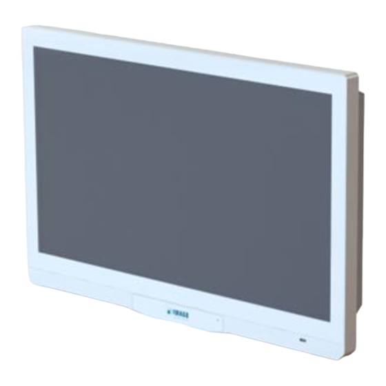
2 Introduction Page 5 / 24 2.1 Key Features The Vision Box Touch has integrated the mainboard of the Vision Box AGE-X5.1 and a 21.5” touch display into one compact housing. The key features are: • Housing IP65 housing design Passive cooling Interfaces behind the VESA 100 mount cover on the back. -
Page 6: Overview
3 Overview Page 6 / 24 3 Overview 3.1 Front-/Display-Side 3.2 Back-/VESA-Mount-Side IMAGO Technologies GmbH Strassheimer Str. 45; 61169 Friedberg - Germany; Tel. +49 6031-6842611 info@imago-technologies.com; www.imago-technologies.com... -
Page 7: Position Of Interface Connectors
(back side view) and all interfaces directly on the AGE-X5.1 mainboard are on the right side. Figure 1: Right Side Interfaces These interfaces are the same in all Vision Box Touch models based on the AGE-X5.1 mainboard. 3.3.2 Left Side On the left side are additional interfaces vary in different configurations. -
Page 8: Basic Features
Page 8 / 24 3.4 Basic features In the table below there are the basic IOs and features that are available in every Vision Box Touch. All Interfaces in this table are on the right side except display and front USB. -
Page 9: Possible Configurations
8× In/ 8× Out isolated Second RTCC Third internal USB 2.0 Unused SATA Unused Table 4: Configuration 2×Gbit Ethernet, 2× 8/8 digIO, 2× Strobe and Camera Trigger IMAGO Technologies GmbH Strassheimer Str. 45; 61169 Friedberg - Germany; Tel. +49 6031-6842611 info@imago-technologies.com; www.imago-technologies.com... -
Page 10: Block Diagram
3 Overview Page 10 / 24 3.6 Block Diagram Figure 3: Block diagram for example configuration from Table 3 IMAGO Technologies GmbH Strassheimer Str. 45; 61169 Friedberg - Germany; Tel. +49 6031-6842611 info@imago-technologies.com; www.imago-technologies.com... -
Page 11: Technical Data
3.7 GHz 4.4 GHz Cores / Threads 2 / 4 6 / 12 8 / 16 35 W 35 W 35 W Table 5: Processor overview IMAGO Technologies GmbH Strassheimer Str. 45; 61169 Friedberg - Germany; Tel. +49 6031-6842611 info@imago-technologies.com; www.imago-technologies.com... -
Page 12: Operating Conditions
Certain possible usage combinations like simultaneous USB device supply and active LED output can lead to contin- uous excess of this value, which must be avoided by the user. IMAGO Technologies GmbH Strassheimer Str. 45; 61169 Friedberg - Germany; Tel. +49 6031-6842611... - Page 13 TTL-compatible option is only available for the second I/O module The maximum current and strobe timing limits are calculated by the software, depending on the used parameters. IMAGO Technologies GmbH Strassheimer Str. 45; 61169 Friedberg - Germany; Tel. +49 6031-6842611...
-
Page 14: Dimensions
4 Technical Data Page 14 / 24 4.3 Dimensions Figure 4: Housing dimensions (in mm) IMAGO Technologies GmbH Strassheimer Str. 45; 61169 Friedberg - Germany; Tel. +49 6031-6842611 info@imago-technologies.com; www.imago-technologies.com... -
Page 15: Power Connector - Right Side
GND to reset the Vision Box during operation. A falling edge will trigger the reset. Leaving the signal floating is the default mode for normal operation. Phoenix Contact plug component: MC 1,5/4-STF-3,5 (order no. 1847071) IMAGO Technologies GmbH Strassheimer Str. 45; 61169 Friedberg - Germany; Tel. +49 6031-6842611 info@imago-technologies.com; www.imago-technologies.com... -
Page 16: Interfaces
6 Interfaces Page 16 / 24 6 Interfaces This chapter describes the interfaces for the Vision Box Touch. 6.1 Ethernet Interface - Right Side (Single) The single Ethernet interface is present for all hardware configurations. • generation CPU: 2.5GbE (2.5GBASE-T) -
Page 17: Displayport Monitor Interface - Right Side
1.5 GB/s. The BIOS can boot from this device, but a card hot swap is not supported. The card edge is be- hind a service flap which can be removed tool-free. Figure 9: CFast with dust protection flap IMAGO Technologies GmbH Strassheimer Str. 45; 61169 Friedberg - Germany; Tel. +49 6031-6842611 info@imago-technologies.com; www.imago-technologies.com... -
Page 18: Digital I/O - Left Side
VCC pin which is used by all output signals. Every input and output have an LED to show the current state of each channel. IMAGO Technologies GmbH Strassheimer Str. 45; 61169 Friedberg - Germany; Tel. +49 6031-6842611... - Page 19 Software must configure the Real-Time Communication Controller to use the same signal source for these outputs. A high-current hardware option for the digital outputs is also available. See section 4.2 Operating Condi- tions for electrical specifications. IMAGO Technologies GmbH Strassheimer Str. 45; 61169 Friedberg - Germany; Tel. +49 6031-6842611 info@imago-technologies.com; www.imago-technologies.com...
- Page 20 Figure 13: Digital I/O example 2 Please note that a flyback diode as shown in the drawing should be used to protect the output circuit from voltage spikes at deactivation. IMAGO Technologies GmbH Strassheimer Str. 45; 61169 Friedberg - Germany; Tel. +49 6031-6842611 info@imago-technologies.com; www.imago-technologies.com...
-
Page 21: Led Controller And Camera Trigger - Left Side
Supply Lighting Unit Strobe ACQ LED - enable Real Time Current Communication Current reference Controller Regulation (FPGA) Current value Sense Figure 15: LED Controller structure IMAGO Technologies GmbH Strassheimer Str. 45; 61169 Friedberg - Germany; Tel. +49 6031-6842611 info@imago-technologies.com; www.imago-technologies.com... -
Page 22: Camera Trigger
VisionBox Figure 16: Simplified camera trigger diagram The high-side switch is connected to the power supply voltage of the VisionBox and has a current-limiting circuit. IMAGO Technologies GmbH Strassheimer Str. 45; 61169 Friedberg - Germany; Tel. +49 6031-6842611 info@imago-technologies.com; www.imago-technologies.com... -
Page 23: Accessories
1847288 Digital In / Out There is also a connector set with plugs available. Please refer to the following table or ask for more de- tails. 7.2 IMAGO Accessories Order Number Description 10100071 Connector set: 1x 4 Pin power connector, 2x 18 Pin I/O... -
Page 24: History
8 History Page 24 / 24 8 History Revision Date Changes Initials 8.2023 First version IMAGO Technologies GmbH Strassheimer Str. 45; 61169 Friedberg - Germany; Tel. +49 6031-6842611 info@imago-technologies.com; www.imago-technologies.com...
Need help?
Do you have a question about the Vision Box Touch and is the answer not in the manual?
Questions and answers