
Related Manuals for Electron Plus SPA100


Summary of Contents for Electron Plus SPA100
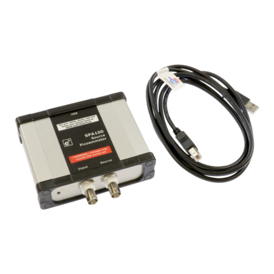
- Page 1 SPA100 User Manual (software version: 24.001) www.electron.plus Copyright © 2018-2024 Electron Plus. All Rights Reserved.
-
Page 2: Table Of Contents
Connecting Instrument ................. 15 Check for updates ..................16 Calibration loading ..................17 Control Ribbon .................... 18 Menu Bar ..................... 18 File ......................19 New topic ....................20 Measuring Resistance ..................20 Technical ......................21 SPA100 Bias Generator ................. 21 2 / 21... -
Page 3: Notices
This manual (or part thereof) may not be reproduced by any means (electronic or photographic, including translation into a foreign language) without prior written consent and agreement from Electron Plus as set-out in United Kingdom and international copyright laws. Electron Plus is a trading style of BFRAD Limited. -
Page 4: Notes
Copying or reproducing this document or any part of this document without written permission of Electron Plus is strictly prohibited. Trademark acknowledgement Electron Plus fully recognises and acknowledges any trademark(s) of the respective trademark holder. Windows is a trademark of Microsoft Corporation... -
Page 5: Getting Started
We recommend at least Windows 7 operating system (however, we know of Windows XP and 32 bit machines working well with EPIC). EPIC is available in both 32 bit and 64 bit from the Electron Plus website. 1x USB 2.0 type A (common) for connection to the instrument, at 0.5A. -
Page 6: Getting Help
SPA100 User Manual Getting help Help is available by email: support@electron.plus If you are experiencing an issue with SPA, please email a copy of the following files (see below) found in the SPA installation folder along with a description of the problem. -
Page 7: Introduction
SPA100 User Manual Introduction Welcome Congratulations and thank you for purchasing an Electron Plus product. Please take a few minutes to read the ‘Before You Start’ section of this manual, especially as misusing this product can result in damage to it, your device-under-test or potentially place you in-danger. -
Page 8: New In Software
SPA100 User Manual New in Software SPA software is specifically for the Electron Plus range of picoammeters, this takes over from the earlier EPIC software suite. Please contact us if you would like copies of previous software versions. 8 / 21... -
Page 9: Installation Sequence
SPA100 User Manual Installation sequence Please install the SPA software and the associated USB driver software BEFORE connecting your device to a computer. You do not need to remove a previous copy of SPA (or EPIC), the new copy will overwrite the necessary existing file(s). -
Page 10: Installing The Software
SPA100 User Manual Installing the Software Electron Plus products require a USB connection to a PC running SPA in order to function. SPA comes in two compiled versions: SPA64 - for 64 bit Windows installations & PC's (we recommend this). -
Page 11: Installing The Usb Driver
SPA100 User Manual Installing the USB driver The product covered in this document communicates with the host PC via USB using an WCH CH340 bridge IC. A copy of the official WCH device driver is available from the SOFTWARE section of our website (www.electron.plus/pages/software), device drivers can also be downloaded... -
Page 12: Earthing For Function And Safety
In this case, we recommend loosening (and re-tightening) the M3 stainless steel chassis screw (2mm HEX drive) and fitting an earthing wire using either ring terminal or spade terminal. If in doubt please contact Electron Plus for further details. Caution USB 0V, rear panel, front panel, casing and any external power supply 0V are all the same potential and connected via low impedances (PCB, metalwork, etc.) - Avoid creating 'ground loops' with your setup! -
Page 13: Operation
SPA100 User Manual Operation Selecting Instrument When SPA is first installed it will initially start in SPA100 mode. To change this: INSTRUMENT > CHANGE INSTRUMENT and select the actual instrument you wish to use, you will then have to close and reopen EPIC for this to take effect. -
Page 14: Selecting Serial Com Port
COM port and save your selection. When you have finished, either close the pop-up window or click the main window (the pop-up will close automatically). Technical Note Each Electron Plus instrument type that uses a COM serial port has it's own entry in "settings.txt", e.g. CTL_ComPort=3 14 / 21... -
Page 15: Connecting Instrument
SPA100 User Manual Connecting Instrument To connect to the instrument you can use the options in the MENU or the button on the CONTROL RIBBON. INSTRUMENT > CONNECT to connect, or DISCONNECT to disconnect. An error message will be displayed if SPA cannot open a serial port to the instrument - this can be caused by the following: 1. -
Page 16: Check For Updates
SPA100 User Manual Check for updates Once per day SPA will check if there is a newer version available. This feature maybe disabled or re-enabled here: UTILITIES > DAILY UPDATE CHECK Tick will enable EPIC to perform the daily update check, unticking will prevent EPIC from performing the daily update check. -
Page 17: Calibration Loading
The status of the background download from the SPA100 is displayed in the Status window (seen below). If a particular SPA100 has not been used with a particular installation of SPA, then the calibration download must complete before accurate results can be obtained. -
Page 18: Control Ribbon
SPA100 User Manual Control Ribbon The following sections are descriptions of Instrument Status, Signature Generator, Test Controls Edit Controls and their functions. Menu Bar 18 / 21... -
Page 19: File
SPA100 User Manual File 19 / 21... -
Page 20: New Topic
SPA100 User Manual New topic Measuring Resistance Resistance is measured by connecting the resistor (or material substrate) between the centre pin of the Source BNC and the centre pin of the Input BNC. Resistance is measured by selecting a known voltage (from the Source). -
Page 21: Technical
Technical SPA100 Bias Generator The bias generator output of the SPA100 is a low power class A amplifier. It is primarily design to provide a bias voltage for photodiodes in low-current measurement situations. The output impedance is 2.7Kohms, this is after the feedback network, so some drop should be expected depending on load impedance.
Need help?
Do you have a question about the SPA100 and is the answer not in the manual?
Questions and answers