Advertisement
Quick Links
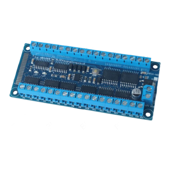
POINTS POSITION INDICATOR PPI-T4
The Points Position Indicator (PPI) monitors the brief switching voltage to either of
the two coils of a points motor, and displays the last operation using coloured leds
that can be mounted on a route mimic.
Monitors the brief operating voltage across points motors when they are switched
Lights a corresponding led on a control panel to show the last operation of each set
of points
Saves all settings automatically to memory when the power is switched off
Monitors up to 8 sets of points
Requires a 12V DC Power Supply
Advertisement

Related Manuals for BLOCKsignalling PPI-T4


Summary of Contents for BLOCKsignalling PPI-T4
- Page 1 POINTS POSITION INDICATOR PPI-T4 The Points Position Indicator (PPI) monitors the brief switching voltage to either of the two coils of a points motor, and displays the last operation using coloured leds that can be mounted on a route mimic.
- Page 2 A positive voltage is momentarily switched to the points to operate them. BLOCKsignalling also make Points Position Indicators for use with points operated from DCC Accessory Decoders (where the points coil common is positive) and 2- wire points (such as Kato) where the DC polarity is reversed to change the direction of the points.
-
Page 3: Power Supply
BLOCKsignalling www.blocksignalling.co.uk Power Supply The module is designed for use with a 12V DC plug-top type power supply. The current consumption is approximately 0.05A (50mA) with all the panel leds lit, and a power supply rated at 0.25A to 1A is recommended. - Page 4 BLOCKsignalling www.blocksignalling.co.uk System Wiring – Single Colour Leds The diagram below shows the connections to one set of points. In practice, connections to the PPI will normally be made at the control panel switches so that the wiring length can be kept to a minimum.
- Page 5 BLOCKsignalling www.blocksignalling.co.uk System Wiring – Dual Colour Leds Dual colour leds can also be used. These consist of two separate leds mounted in a single package. Generally, these type of leds will have a resistor included in their wiring, otherwise a 1k resistor must be connected in series with each led.
-
Page 6: Module Leds
BLOCKsignalling www.blocksignalling.co.uk Module Leds When powering up, the uP (red) led on the pcb will light (and remain lit) whilst the microprocessor is running. Each time a point is operated, the IP (yellow) led flashes to confirm the input signal. -
Page 7: Led Connection
BLOCKsignalling www.blocksignalling.co.uk Led Connection When connecting leds it is important to connect them the right way around. The negative lead (cathode) is identified by a flat on the side of the led body, and by having a shorter lead. Each led requires a resistor in series with the output limit the led current. A resistor value of 1k will generally be suitable. - Page 8 BLOCKsignalling www.blocksignalling.co.uk Important The high current wiring to the points motors can cause interference to the operation of the low power led wiring. When building the control panel, take care to keep the low and high power wiring separate at the control panel and between the control panel and the PPI.
- Page 9 BLOCKsignalling www.blocksignalling.co.uk Troubleshooting the PPI (Test 1) If you are having a problem getting the PPI to work as you expect, this part of the document should help. Each PPI is tested before shipping, so it is unlikely the module itself is at fault but this document should allow you to check for correct function of the module, power supply and external wiring.
- Page 10 BLOCKsignalling www.blocksignalling.co.uk Testing the Points Inputs (Test 2) The connections to the points are electrically isolated from the control electronics within the PPI, so the main PPI power feed is not required for this test. Using a DC supply of around 12V (a 9V battery is also suitable), connect one side of the supply to the COM terminal and using the other wire, connect it to each input terminal in turn.
- Page 11 BLOCKsignalling www.blocksignalling.co.uk Testing the Led Outputs (Test 3) If the button is pressed whilst the PPI is running, it will perform a led test sequence. All the leds are extinguished, then the led connected to A1 is lit for 1 second. Then the led connected to A2 is lit.
- Page 12 BLOCKsignalling www.blocksignalling.co.uk Testing the Memory Function (Test 4) This test is the final check that the module is operating correctly. It repeats the previous tests, but confirms that the microprocessor memorises when points are changed. Connect up the output leds.
- Page 13 BLOCKsignalling www.blocksignalling.co.uk FULL TEST 12V DC POWER SUPPLY MOVE CONNECTION ALONG TO TOUCH EACH TERMINAL BATTERY 1. CONNECT UP POWER SUPPLY AND LEDS ON THE OUTPUT 2. SWITCH ON POWER SUPPLY 3. RED LED FLASHES FOR 1 SECOND 4. RED LED STAYS LIT 5.
- Page 14 BLOCKsignalling www.blocksignalling.co.uk Other Tips & Tricks Occasionally, the PPI may be found to restart itself after high power accessories are operated (such as un-couplers) where a large current flows. When a high current flows in a wire, magnetic and electric fields are created which can cause interaction with adjacent wiring.
Need help?
Do you have a question about the PPI-T4 and is the answer not in the manual?
Questions and answers