Advertisement
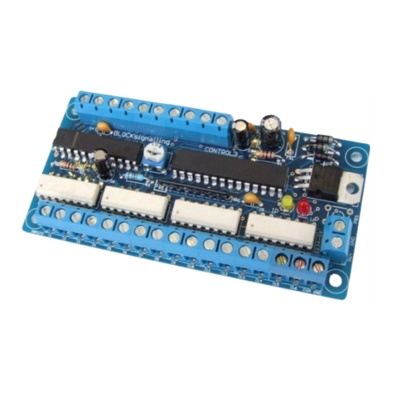
POINTS POSITION INDICATOR PPI4
Advanced PPI with Adjustable Brightness & Simplified Wiring
Monitors the brief positive operating voltage across points motors when they are switched
Lights a corresponding led on a control panel to show the last operation of each set of points
Saves all settings automatically to memory when the power is switched off
Monitors up to 8 sets of points
Opto-isolated inputs accept voltages from +5V to +60V
The Points Position Indicator (PPI) monitors the brief switching voltage to either of the two
coils of a points motor, and displays the last operation using coloured leds which can be
mounted on a route mimic.
Manual methods to switch points include simple spring-loaded switches, push buttons, probe
and stud, etc and the points coils have a common connection to the ground of the supply.
When points are driven from DCC Accessory decoders, the decoders most often provide a
+12V supply to the common of the points coil, and then switch the other connections of the
coils to ground to switch the points (use PPI2-DCC with these).
Advertisement
Table of Contents

Related Manuals for BLOCKsignalling PPI4


Summary of Contents for BLOCKsignalling PPI4
- Page 1 POINTS POSITION INDICATOR PPI4 Advanced PPI with Adjustable Brightness & Simplified Wiring Monitors the brief positive operating voltage across points motors when they are switched Lights a corresponding led on a control panel to show the last operation of each set of points ...
- Page 2 This PPI is designed for operation on systems where the coil common is GROUND. The microprocessor controls the led brightness and so no resistors are required, simplifying wiring up. Power Supply The controller is designed for use with a DC power supply of between 10V and 25V, or an AC power supply of between 10V and 16V.
- Page 3 The PPI also requires a power supply to operate the leds. The supply can be AC or DC, and must be in the range of 9V to 16V for correct operation. If using a DC supply, take care to connect the positive and negative leads correctly. No harm will be done to the PPI if they are connected in reverse, but the PPI will not function.
- Page 4 Led Connection When using leds it is important to connect them the right way around. The negative lead (cathode) is identified by a flat on the side of the led body, and by having a shorter lead. The red and green leds share the same output, so for instance, the first set of points are represented by a red and green led with their anodes connected to terminal A1+.
- Page 5 Following factory testing, sometimes more than one led will be lit. This will clear as soon as each set of points is first operated.
- Page 6 System Wiring The diagram below shows the connections to one set of points. In practice, connections to the PPI will normally be made at the control panel so that the wiring length can be kept to a minimum.
Need help?
Do you have a question about the PPI4 and is the answer not in the manual?
Questions and answers