
Related Manuals for NORTHERN ELECTRIC BDM-1000


Summary of Contents for NORTHERN ELECTRIC BDM-1000
- Page 1 BDM-1000 Installation User Manual Northern Electric Power Co,. Ltd. V2.0 rev.2023.2.10...
- Page 2 DISCLAIMERS The information in these documents is the property of Northern Electric Power Co., Ltd., hereafter referred to as NEP. No part of this document may be reproduced, stored in a retrieval system, or transmitted, in any form or by any means, mechanical, electronic, photographic, magnetic or otherwise, without the prior written permission of NEP.
-
Page 3: Information On This Document
INFORMATION ON THIS DOCUMENT Target Group This document is intended for “Qualified Persons" and "End Users". Tasks marked with a warning symbol and the caption “Qualified Persons” require associated skills to avoid and deal with the dangers and risks in installing and using the product and tools described in this document. Tasks not marked do not require particular qualifications and skill sets, and therefore can be performed by end users. -
Page 4: Warning Messages
For technical problems concerning the products in this document and requiring assistance, please refer to CONTACT. Copyright © 2021 Northern Electric Power Co,. Ltd.. All rights reserved. Warning Messages The following warning messages are used in this document, and should be familiarized before installation or operation of the product. -
Page 5: Fcc Compliance
FCC COMPLIANCE This equipment has been tested and found to comply with the limits for a Class B digital device, pursuant to part 15 of the FCC Rules. These limits are designed to provide reasonable protection against harmful interference in a residential installation. - Page 6 Danger to life due to electrical shock in case of over-voltages and missing surge protections Over-voltages may conduct into other properties (e.g. electrical network of the building, connected devices via network cables or data cables) in the event of a flash or lightning strike when there is no surge protection integrated in the system.
- Page 7 Risk of injury and property damage due to inappropriate modifications or technical specifications Modifications or alterations to the product and its connected system are not allowed unless with written permission of NEP. Unauthorized modifications may cause incompliance with product's technical requirement (e.g. maximum input voltage or current), that may result in moderate or minor injuries, and property damages.
- Page 8 The product must ONLY be connected and operated with PV arrays of protection class II, in accordance with IEC 61730, application class A. The PV modules must also be compatible with this product. Power sources other than compatible PV arrays MUST not be connected and operate with the product. ...
-
Page 9: Product Overview
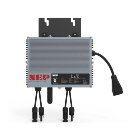
OVERVIEWING THE PRODUCT Product Overview AC Output Terminal WiFi Dongle (optional) LED display DC input 1 (+) DC input 1 (-) DC input 2 (+) DC input 2 (-) Identifying the Product Serial Number (S/N) SN is on the sticker which place right bottom corner of the product. Symbols on the label ... - Page 10 INFO denotes information that is important but non safety-relevant for a task or topic. Label is located on the side of the inverter. The information on the label includes technical data as well as type and serial number of the device. Safety instructions are listed and explained below: Danger! The term “danger”...
-
Page 11: Installing The Product
INSTALLING THE PRODUCT Safety Danger to life due to fire or explosion All electrical devices can cause fires despite careful construction. Flying debris from the fire or explosion may result in death or severe injuries. DO NOT install the product in environment with any flammable materials or gases. DO NOT install the product in environment with any potentially explosive items or gases. -
Page 12: Parts Required
Lightning Surge Suppression Lightning does not actually need to strike the equipment or building where PV system is installed to cause damage. Often, a strike nearby will induce voltage spikes in the electrical grid that can damage equipment. micro inverter has integrated surge protection, greater than most string inverters. - Page 13 To only install one inverter or BALCONY SOLUTION Please follow the sign...
-
Page 14: Connecting The Product
CONNECTING THE PRODUCT Safety: Electrical Connections Danger to life due to electric shock DO NOT touch any live component. TO prevent risk of electric shock during installation and maintenance, please make sure that the AC and DC inputs are plugged out. DO NOT stay close to the instruments while there is severe weather conditions including storm, lightening etc. - Page 15 Mount one micro inverter at each of these locations using hardware recommended by your module racking vendor STEP 3 - Inter-connect Micro inverters into branch Each product comes with one AC output cable with T-connection connector at the end. Plug the AC connector of the each product into socket on the Trunk Cable to form a continuous AC branch circuit.
- Page 16 STEP 5 - Ground the system through racking (option) BDM-1000 may also be grounded through the racking. STEP 6 - Complete the connection map and connect the PV Modules A connection map is a diagrammatic representation of the physical location of each micro inverter in your PV installation.
- Page 17 Personal protective equipment MUST be worn suitably and properly for all work on the product and the system. Voltage sources MUST be disconnected from the product before all work. Danger to life due to electrical shock from touching ungrounded components or from touching live components in case of a ground fault ...
- Page 18 socket) of the micro inverter. Repeat for all remaining PV modules using one micro inverter for each module. Removing DC Safety: Disconnection Danger to life due to electrical shock when live components are touched in opened product High voltages and energies are present in live components and cables inside the product during operation, e.g. capacitors, connectors.
- Page 19 Procedure of Disconnecting Before any work on the disconnection of the inverter, ALWAYS disconnect it from all voltage sources in the described sequence as following. 1. Disconnect the AC by opening the branch circuit breaker. 2. Disconnect the first AC connector in the branch circuit. 3.
- Page 20 connector (female socket) of the micro inverter. Repeat for all remaining PV modules using one micro inverter for each module. 4. Replace the old PLC_ID in the BDG-256 gateway with the new PLC_ID of the replacement micro inverter.
- Page 21 COMMISSIONING CONNECT micro inverter TO THE ELECTRICAL UTILITY GRID ONLY AFTER RECEIVING PRIOR APPROVAL FROM THE UTILITY COMPANY. BE AWARE THAT ONLY QUALIFIED PERSONNEL CAN CONNECT micro inverter TO THE ELECTRICAL UTILITY GRID. ENSURE THAT ALL AC AND DC WIRING IS CORRECT. ENSURE THAT NONE OF THE AC AND DC WIRES IS PINCHED OR DAMAGED.
-
Page 22: Troubleshooting
TROUBLESHOOTING In case of fault, BDM inverter has multiple protective functions and stops output power. The fault message may be sent to a connected BDG-256 gateway through power line communication. For BDM-WiFi, the same alert is sent through WiFi internet connection, and can be monitored through NEPViewer (please refer to the tech note “Configuring BDM WiFi”). The alert message is a 16-bit code. -
Page 23: Recycling And Disposal
ALWAYS DISCONNECT AC POWER BEFORE DISCONNECTING PV MODULE WIRES FROM micro inverter. THE AC CONNECTOR OF THE FIRST micro inverter IN A BRANCH CIRCUIT IS SUITABLE AS A DISCONNECTING MEANS ONCE THE AC BRANCH CIRCUIT BREAKER IN THE LOAD CENTER HAS BEEN OPENED. Troubleshooting an inoperable BDM micro inverter To troubleshoot an inoperable micro inverter, follow the steps in the order shown: 1. -
Page 24: Product Parameters
PRODUCT PARAMETERS Input | DC BDM-800 BDM-1000 Recommended PV Module Power Range / W 600 x 2 750 x 2 MPPT Voltage Range / V 22-55 22-55 Startup Voltage / V Max. Input Voltage / V Max. Input Current / A... - Page 25 BDM-1000 BDM-800 BDM-1000 DC Connector Type AC Connection Type (inverter-inverter) Trunk Cable Trunk Cable Communication Method PLC or WiFi PLC or WiFi Protection Class NEMA-6 / IP-66 / IP-67 NEMA-6 / IP-66 / IP-67 The AC voltage/Frequency range may vary depending on specific country grid ...
Need help?
Do you have a question about the BDM-1000 and is the answer not in the manual?
Questions and answers