Table of Contents
Advertisement
Advertisement
Table of Contents

Related Manuals for NORTHERN ELECTRIC BDM-2000


Summary of Contents for NORTHERN ELECTRIC BDM-2000
- Page 1 BDM-2000 Installation User Manual V2.0 rev.2023.2.10 Manufacturer Suzhou Northern Electric Power Technology Co.,Ltd Kangzhen Building, No. 18, Louyang Road, Suzhou Industrial Park,P.R.China Email: support_dach@northernep.com support_eu@northernep.com Web: https://eu.northernep.com...
- Page 2 DISCLAIMERS The information in these documents is the property of Northern Electric Power Co., Ltd., hereafter referred to as NEP. No part of this document may be reproduced, stored in a retrieval system, or transmitted, in any form or by any means, mechanical, electronic, photographic, magnetic or otherwise, without the prior written permission of NEP.
-
Page 3: Information On This Document
INFORMATION ON THIS DOCUMENT Target Group This document is intended for “Qualified Persons" and "End Users". Tasks marked with a warning symbol and the caption “Qualified Persons” require associated skills to avoid and deal with the dangers and risks in installing and using the product and tools described in this document. -
Page 4: Warning Messages
For technical problems concerning the products in this document and requiring assistance, please refer to CONTACT. Copyright © 2021 Northern Electric Power Co,. Ltd.. All rights reserved. Warning Messages The following warning messages are used in this document, and should be familiarized before installation or operation of the product. - Page 5 denotes a hazardous situation which, if not avoided, will result in death or severe DANGER injury. denotes a hazardous situation which, if not avoided, can result in death or severe or WARNING moderate injury. denotes a hazardous situation which, if not avoided, can result in moderate or minor CAUTION injury.
-
Page 6: Fcc Compliance
FCC COMPLIANCE This equipment has been tested and found to comply with the limits for a Class B digital device, pursuant to part 15 of the FCC Rules. These limits are designed to provide reasonable protection against harmful interference in a residential installation. This equipment generates uses and can radiate radio frequency energy and, if not installed and used in accordance with the instructions, may cause harmful interference to radio communications. - Page 7 Danger to life due to electrical shock when live DC cables or components are touched High DC voltages are present in the DC cables when PV modules are exposed to light. Touching live DC cables or components may result in death or severe injuries due to electric shock. touch non-insulated parts or cables.
- Page 8 touch any parts or frame of the PV array. DO NOT touch any cables without reliable insulation. DO NOT connect the product to any strings with ground faults. DO NOT Before working on the product, voltage resources MUST be disconnected. Personal protective equipment MUST be worn suitably and properly for all work.
- Page 9 Risk of injury due to hot enclosures Touching parts of product enclosure that may get hot during operation (e.g. heatsink) and may result in burn injuries. touch any parts other than the cover lid of the product. DO NOT Before working on the product, voltage resources MUST be disconnected, and leave the product to cool down for 30 minutes.
- Page 10 The product must ONLY be connected and operated with PV arrays of protection class II, in accordance with IEC 61730, application class A. The PV modules must also be compatible with this product. Power sources other than compatible PV arrays MUST not be connected and operate with the product.
-
Page 11: Product Overview
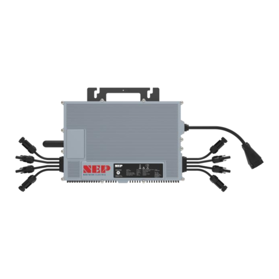
OVERVIEWING THE PRODUCT Product Overview AC Output Terminal WiFi Dongle (optional) LED display DC input 1 (+) DC input 1 (-) DC input 2 (-) DC input 2 (+) DC input 3 (+) DC input 3 (-) DC input 4 (-) DC input 4 (+) -
Page 12: Identifying The Product
Identifying the Product Serial Number (S/N) SN is on the sticker which place right bottom corner of the product. Symbols on the label denotes information that is important but non safety-relevant for a task or topic. INFO Label is located on the side of the inverter. The information on the label includes technical data as well as type and serial number of the device. -
Page 13: Installing The Product
INSTALLING THE PRODUCT Safety Danger to life due to fire or explosion All electrical devices can cause fires despite careful construction. Flying debris from the fire or explosion may result in death or severe injuries. install the product in environment with any flammable materials or gases. DO NOT install the product in environment with any potentially explosive items or gases. -
Page 14: Parts Required
install the product in exposure to rain and snow. DO NOT install the product in exposure to splash of salt water. DO NOT Make sure the installation site meets ventilation requirement of the product. The pollution degree of the external environment for NEP's inverters is PD3. Pollution Degree 3 indicates: Conductive pollution occurs, or dry, non-conductive pollution occurs which becomes conductive due to condensation which is expected. - Page 15 1. Measuring service and installing the AC branch circuit junction box. ONLY USE ELECTRICAL SYSTEM COMPONENTS APPROVED FOR WET LOCATIONS. 2. Attaching the micro inverter Micro inverter to the racking. 3. Connecting the micro inverter Micro inverter wiring harnesses. 4. Grounding the system (optional). DC circuits of micro inverter are isolated and insulated from ground.
-
Page 16: Connecting The Product
CONNECTING THE PRODUCT Safety: Electrical Connections Danger to life due to electric shock DO NOT touch any live component. TO prevent risk of electric shock during installation and maintenance, please make sure that the AC and DC inputs are plugged out. DO NOT stay close to the instruments while there is severe weather conditions including storm, lightening etc. - Page 17 STEP 2 - Attach product to the Racking Mark the approximate centers of each PV module on the racking system. Evaluate the location of the micro inverter with respect to the PV module junction box or any other obstructions. ALLOW A MINIMUM OF .75 INCHES BETWEEN THE TOP OF THE ROOF AND THE BOTTOM OF micro inverter.
-
Page 18: Step 4 - Ground The System
STEP 4 – Ground the system Each product has an integrated ground protection circuit. The grounding wire is through the trunk cable, and should be securely connected to the ground connector in the junction box. STEP 5 - Ground the system through racking (option) BDM-1000 may also be grounded through the racking. - Page 19 touch live components when voltage sources are still connected or just DO NOT disconnected. connect DC connectors to the product under load. DO NOT Personal protective equipment MUST be worn suitably and properly for all work on the product and the system. Voltage sources MUST be disconnected from the product before all work.
- Page 20 For connection of PV modules to the inverter, all PV modules MUST be fitted with the supplied DC connectors. When assembling the DC connectors, cables MUST be equipped with DC connectors of the correct polarity. e.g. [positive] connection cable to [positive] DC connectors, [negative] connection cable to [negative] DC connectors.
- Page 21 High voltages and energies are present in live components and cables inside the product during operation, e.g. capacitors, connectors. Touching live components and cables may result in death or severe injuries due to electric shock. open the product. DO NOT touch live components.
- Page 22 Procedure of Disconnecting Before any work on the disconnection of the inverter, ALWAYS disconnect it from all voltage sources in the described sequence as following. 1. Disconnect the AC by opening the branch circuit breaker. 2. Disconnect the first AC connector in the branch circuit. 3.
- Page 23 Re-install micro inverter 1. Attach the replacement micro inverter to the PV module racking using hardware recommended by your module racking vendor 2. Connect the AC cable of the replacement micro inverter and the neighboring micro inverter to complete the branch circuit connections. 3.
-
Page 24: Commissioning Procedure
COMMISSIONING CONNECT micro inverter TO THE ELECTRICAL UTILITY GRID ONLY AFTER RECEIVING PRIOR APPROVAL FROM THE UTILITY COMPANY. BE AWARE THAT ONLY QUALIFIED PERSONNEL CAN CONNECT micro inverter TO THE ELECTRICAL UTILITY GRID. ENSURE THAT ALL AC AND DC WIRING IS CORRECT. ENSURE THAT NONE OF THE AC AND DC WIRES IS PINCHED OR DAMAGED. - Page 25 An eight-digit string can be found under the barcode on the sticker. This is the AP Number Step 1 Connect to AP From a PC (MAC/WINDOWS) or a smart phone find such Wifi Hotspot in your Wifi list Connect the Hotspot with password: 12345678 Step 2 Access to AP admin page Visit such address in your web browser...
- Page 26 Select your home WIFI SSID and click on OK Enter WIFI password and click on OK Plug inverter AC into wall socket, WiFi is connected. Data will start uploading to cloud after minutes. Step 4 Get and Open NEPViewer Obtain NEPViewer App Search for NEPViewer in App Store or Google Play * Android users can visit user.nepviewer.com...
- Page 27 Open NEPViewer...
- Page 28 Add inverter to NEPViewer Login or Register Click here to create a new site...
- Page 29 Gateway (PLC) or WiFi, can be added in the form of GATEWAY CODE On label of the inverter, a serial number can be found under the bar code, in form of: XXXXX-XXXXXXXX-X This EIGHT-digit-code is the GATEWAY CODE Fill in other detail info about your site and click on Next Give a name to your site, and fill in GeoLocation click on Next...
- Page 30 Fill in preferences Site added when this dialog shown...
- Page 31 It's all set! Enjoy your PV freedom! Start Power Generation Following these steps to commission the micro inverter PV system: 1. Turn on the AC disconnects or circuit breakers on each micro inverter AC branch circuit. 2. Turn on the main utility-grid AC circuit breaker. Your system will start producing power after a few minutes wait time.
- Page 32 Status Meaning Green Light Flashing every one seconds Producing Standby Red Light Solid Producing Grounding Fault Orange Light Flashing every one seconds Producing no communication with BDG-256...
-
Page 33: Troubleshooting
TROUBLESHOOTING In case of fault, BDM inverter has multiple protective functions and stops output power. The fault message may be sent to a connected BDG-256 gateway through power line communication. For BDM- WiFi, the same alert is sent through WiFi internet connection, and can be monitored through NEPViewer (please refer to the tech note “Configuring BDM WiFi”). - Page 34 NEVER DISCONNECT THE DC WIRE CONNECTORS UNDER LOAD. ENSURE THAT NO CURRENT IS FLOWING IN THE DC WIRES PRIOR TO DISCONNECTING. AN OPAQUE COVERING MAY BE USED TO COVER THE MODULE PRIOR TO DISCONNECTING. PRODUCT IS POWERED BY DC POWER FROM PV MODULES. MAKE SURE YOU DISCONNECT THE DC CONNECTIONS AND RECONNECT DC POWER TO WATCH FOR THE TWO SECONDS LED ON AND TWO SECONDS LED OFF AFTER DC IS APPLIED.
- Page 35 BDM systems close by, it is highly recommended to install LCF for each micro inverter system to block interference from adjacent other systems. 8. If the problem persists, please call customer support at NEP. DO NOT ATTEMPT TO REPAIR THE micro inverter; IT CONTAINS NO USER-SERVICEABLE PARTS. IF TROUBLESHOOTING METHODS FAIL, PLEASE RETURN THE micro inverter TO YOUR DISTRIBUTOR FOR MAINTENANCE.
-
Page 36: Recycling And Disposal
RECYCLING AND DISPOSAL In requirement of WEEE, dispose the product using methods that are in accordance with local regulations for electronic waste The product described in this document is involved and categorized in the regulations of Waste Electrical and Electronic Equipment (WEEE) from the European Community Directive 2012/19/EU. -
Page 37: Product Parameters
PRODUCT PARAMETERS Input | DC BDM-2000 Recommended PV Module Power Range / W 750 x 4 MPPT Voltage Range / V 22-55 Startup Voltage / V Max. Input Voltage / V Max. Input Current / A 18 x 4 Overvoltage Protection Category... -
Page 38: General Data
Web: httoseu.northernep.com BDM-2000 Night Power Consumption / mW General Data BDM-2000 Operating Ambient Temperature Range / ℃ -40~65 Relative Humidity Range 0-100% Dimensions (W x H x D) / mm 268 x 250 x 42 Weight / kg DC Connector Type...
Need help?
Do you have a question about the BDM-2000 and is the answer not in the manual?
Questions and answers