Protocol Insight HS-G5 Quick Start And User Manual
Hide thumbs
Also See for HS-G5:
- Quick start and user manual (13 pages) ,
- Quick start user manual (14 pages)
Table of Contents
Advertisement
Quick Links
HS-G5 Interposer (FG5AMPGR) – Rev B
Copyright © Protocol Insight. All rights reserved. Licensed software products are owned by Protocol
Insight or its suppliers and are protected by national copyright laws and international treaty
provisions.
Protocol Insight products are covered by U.S. and foreign patents, issued, and pending. Information
in this manual supersedes all previously published material. Details, specifications, and pricing
subject to change.
Protocol insight is a registered trademark of Protocol Insight, LLC.
MIPI and the MIPI logo are a licensed trademark of the MIPI Alliance.
UFSA and UFS Logo are a trademark of the Universal Flash Storage Association
JEDEC® and the JEDEC logo are registered trademarks of JEDEC Solid State Technology Association.
Contact Protocol Insight at:
sales@protocolinsight.com
support@protocolinsight.com
www.protocolinsight.com
Product specifications and descriptions in this document are subject to change without notice.
Quick Start / User Guide
© Protocol Insight, LLC 2022, Revision 1.3.0, February 2024
1
Advertisement
Table of Contents

Related Manuals for Protocol Insight HS-G5

Summary of Contents for Protocol Insight HS-G5
- Page 1 HS-G5 Interposer (FG5AMPGR) – Rev B Quick Start / User Guide Copyright © Protocol Insight. All rights reserved. Licensed software products are owned by Protocol Insight or its suppliers and are protected by national copyright laws and international treaty provisions.
-
Page 2: Table Of Contents
Offset Cancellation Field Calibration Procedure ................14 Board Dimensions ............................. 15 Phase-Matched Cables ..........................16 Operating Conditions..........................17 Contact Information ..........................17 Product specifications and descriptions in this document are subject to change without notice. © Protocol Insight, LLC 2022, Revision 1.3.0, February 2024... -
Page 3: Introduction
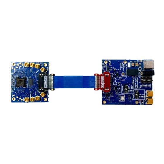
Introduction The HS-G5 Interposer board, FG5AMPGR, allows developers to tap signals between the Host and DUT and send them to a protocol analyzer using SMP-mini connectors. The UFS device is placed directly on the interposer board in a grypper socket. The interposer can be soldered directly into the customer system, or you can use a dual grypper socket connection. - Page 4 UFS device. Figure 2 - Interposer and Power Board with Ribbon Cable (top side view) Product specifications and descriptions in this document are subject to change without notice. © Protocol Insight, LLC 2022, Revision 1.3.0, February 2024...
- Page 5 UFS device by gripping the solder balls. This is depicted on the right side of IGURE Figure 5 - Board Stack-up Example Product specifications and descriptions in this document are subject to change without notice. © Protocol Insight, LLC 2022, Revision 1.3.0, February 2024...
-
Page 6: Use Case Requirements
● Maximum differential signal amplitude 620 mVpp. Figure 6 shows the EYE diagram requirements at the connection point. Figure 6 - EYE Diagram Product specifications and descriptions in this document are subject to change without notice. © Protocol Insight, LLC 2022, Revision 1.3.0, February 2024... -
Page 7: Connecting The Lnterposer Board To The Protocol Analyzer
Sublink 0 Rx0 and Rx1, respectively. DOUT0 and DOUT1 should be connected to Sublink 1 Rx0 and Rx1, respectively. Product specifications and descriptions in this document are subject to change without notice. © Protocol Insight, LLC 2022, Revision 1.3.0, February 2024... -
Page 8: Controls And Status
If the red status light is illuminated, power cycle the unit by removing and then reinserting the USB- C power cable. Product specifications and descriptions in this document are subject to change without notice. © Protocol Insight, LLC 2022, Revision 1.3.0, February 2024... -
Page 9: Mode
When the button is pressed to stop the calibration, the current calibration value is written to non- volatile memory, indicated by three blinks on the Memory LED. TATE Mode D Unused: is not implemented. Product specifications and descriptions in this document are subject to change without notice. © Protocol Insight, LLC 2022, Revision 1.3.0, February 2024... -
Page 10: Channel
If you are in factory-default offset calibrations values will be applied. Product specifications and descriptions in this document are subject to change without notice. © Protocol Insight, LLC 2022, Revision 1.3.0, February 2024... -
Page 11: Bit Table
Bit Table Setting – Mode C (Offset Calibration) Increase Decrease (Increment Direction) Small Large (Increment Step Size) [ 6:0 ] Unused Unused Product specifications and descriptions in this document are subject to change without notice. © Protocol Insight, LLC 2022, Revision 1.3.0, February 2024... -
Page 12: Recording Traffic
Recording Traffic You can use the Instrument Status counters in the Protocol Insight software to adjust the grypper interposer lane amplifier settings. You can also use the Smart Tune™ equalization settings to further optimize the lanes. After the Falcon G500C/G550C Analyzer and FG5AMPGR Grypper Interposer are properly set up you can capture traces. -
Page 13: Maintenance - Offset Cancellation
DIN1 5. Repeats steps 3 and 4 for the DIN outputs. If the absolute value of the measured offset voltage for either DOUT or DIN is greater than 3mV, please contact Protocol Insight technical support, refer to ONTACT NFORMATION The support team may direct you to follow the... -
Page 14: Offset Cancellation Field Calibration Procedure
9. Once all lanes have been calibrated, unplug the power cable and reinsert it. 10. Follow the to verify the offset voltages are FFSET ANCELLATION ERIFICATION ROCEDURE within specification. Product specifications and descriptions in this document are subject to change without notice. © Protocol Insight, LLC 2022, Revision 1.3.0, February 2024... -
Page 15: Board Dimensions
1, the interposer board is outlined in yellow and the power board is outlined in IGURE orange. 1.840 in 1.470 in 1.530 in Figure 8 - Board Dimensions Product specifications and descriptions in this document are subject to change without notice. © Protocol Insight, LLC 2022, Revision 1.3.0, February 2024... -
Page 16: Phase-Matched Cables
Min Bend Radius Dynamic 23.3 mm Temperature Range -55 – 125 C Figure 9 - Cable Loss Over Frequency Product specifications and descriptions in this document are subject to change without notice. © Protocol Insight, LLC 2022, Revision 1.3.0, February 2024... -
Page 17: Operating Conditions
2. Support materials and examples files are available at http://www.protocolinsight.com/support-materials/ 3. For technical support please contact your local Protocol Insight representative or support@protocolinsight.com Product specifications and descriptions in this document are subject to change without notice. © Protocol Insight, LLC 2022, Revision 1.3.0, February 2024...
Need help?
Do you have a question about the HS-G5 and is the answer not in the manual?
Questions and answers