
Subscribe to Our Youtube Channel
Related Manuals for Moxa Technologies RKP-C110 Series


Summary of Contents for Moxa Technologies RKP-C110 Series
- Page 1 RKP-C110 Series Hardware User Manual Version 1.0, January 2024 www.moxa.com/products © 2024 Moxa Inc. All rights reserved.
- Page 2 RKP-C110 Series Hardware User Manual The software described in this manual is furnished under a license agreement and may be used only in accordance with the terms of that agreement. Copyright Notice © 2024 Moxa Inc. All rights reserved. Trademarks The MOXA logo is a registered trademark of Moxa Inc.
-
Page 3: Table Of Contents
Table of Contents Introduction ............................5 Overview .............................. 5 Package Checklist ..........................5 Product Features ........................... 5 Hardware Specifications ......................... 6 Hardware Introduction ......................... 7 Appearance ............................7 Front View ............................. 7 Rear View ............................8 Dimensions ............................8 LED Indicators ............................9 Reset Button ............................ - Page 4 Discard Changes .......................... 40 Enabling AMT ............................40 Using Active Management Technology (AMT) ................... 44 Administering Secure Boot ........................45 Enabling UEFI Secure Boot ......................45 Enroll EFI Image .......................... 46 Enroll Customer Key ........................47 Upgrading the BIOS ..........................48 Safety Installation Instructions ......................
-
Page 5: Introduction
Overview The RKP-C110 Series rackmount computers are powered by a 11th Gen Intel® Celeron® or Intel® Core™ i5, or i7 processor. The computers come with a rich set of interface options including up to 10 software- selectable RS-232/422/485 serial ports, up to 12 Gigabit Ethernet ports, and 8 digital inputs and 8 digital outputs. -
Page 6: Hardware Specifications
Hardware Specifications NOTE The latest specifications for Moxa’s products can be found at https://moxa.com. RKP-C110 Series Hardware User Manual... -
Page 7: Hardware Introduction
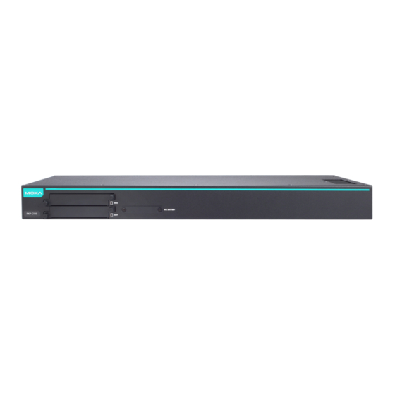
2. Hardware Introduction In this chapter, we provide information about the RKP-C110 computer’s hardware components. Appearance Front View RKP-C110-C1-T/RKP-C110-C5-T/RKP-C110-C7-T Models RKP-C110-C1-8L-T/RKP-C110-C5-8L-T/RKP-C110-C7-8L-T Models RKP-C110-C1-8C-T/RKP-C110-C5-8C-T/RKP-C110-C7-8C-T Models RKP-C110 Series Hardware User Manual... -
Page 8: Rear View
RKP-C110-C1-2L4C-T/RKP-C110-C5-2L4C-T/RKP-C110-C7-2L4C-T Models Rear View Dimensions RKP-C110 Series Hardware User Manual... -
Page 9: Led Indicators
Contact a qualified Moxa support engineer if you have any questions about the RTC battery. ATTENTION There is a risk of explosion if the battery is replaced by a battery of the incorrect type. RKP-C110 Series Hardware User Manual... -
Page 10: Hardware Connections
If the mounting ears are not installed, use four screws each to attach the mounting ears on both sides of the computer. Step 2: Place the computer on a rack and use another four screws to secure the rack-mount ears to the rack. RKP-C110 Series Hardware User Manual... -
Page 11: Connecting The Power
12 VDC at a maximum of 7.34 A, or 24 VDC at a maximum of 3.4 A, and minimum Tma=60˚C. If you need assistance with purchasing a power adapter, contact the Moxa technical support team. RKP-C110 Series Hardware User Manual... -
Page 12: Wiring Requirements
Be sure to disconnect the power cord before installing and/or wiring your device. Electrical Current Caution! Calculate the maximum possible current in each power wire and common wire. Observe all electrical codes dictating the maximum current allowable for each wire size. RKP-C110 Series Hardware User Manual... -
Page 13: Ethernet Ports
The RKP-C110 comes with 2, 6, or 10 software-selectable RS-232/422/485 serial ports with DB9 connectors, which are located on the front panel. The pin assignments are shown below: RS-232 RS-422 RS-485 (2-wire) TxDA(-) – TxDB(+) – RxDB(+) DataB(+) RxDA(-) DataA(-) – – – – – – RKP-C110 Series Hardware User Manual... -
Page 14: Digital Inputs/Digital Outputs
The RKP-C110 comes with two storage slots that allow users to install two 2.5” SATA HDD/SSD. The slots are located on the rear panel of the computer. Follow these steps to install a storage disk. RKP-C110 Series Hardware User Manual... - Page 15 Pull out the storage tray and find the four screws included in the product package. Place the storage disk on the tray. Ensure that the storage disk aligns with the screws on the storage tray. RKP-C110 Series Hardware User Manual...
- Page 16 Reverse the storage tray and fasten four screws to secure the storage drive to the tray. Insert the storage tray into the slot and secure the tray in place with two screws. Use the same method to install a storage disk in the other slot. RKP-C110 Series Hardware User Manual...
-
Page 17: Connecting To Displays
The battery is attached to the slot cover as indicated in the image. Unplug the connector of the battery-cover assembly from the internal wire of the slot. Remove the two screws on the metal plate attached to the battery holder. RKP-C110 Series Hardware User Manual... - Page 18 To reduce the risk of fire or burns, do not disassemble, crush, or puncture the battery; do not dispose of in fire or water and do not short external contacts. RKP-C110 Series Hardware User Manual...
-
Page 19: Bios Setup
Boot From File: Select the UEFI boot up file • Setup Utility: Enter the BIOS configuration menu • Intel® Management Engine BIOS Extension: Enter the AMT configuration menu • Select F2 to enter the BIOS configuration. RKP-C110 Series Hardware User Manual... - Page 20 The BIOS configuration screen will be shown when you enter the Setup Utility option, as shown in the following figure. NOTE The Processor Type information will vary depending on the computer model that you have purchased. RKP-C110 Series Hardware User Manual...
-
Page 21: Main Page
Main Page The Main page displays basic system hardware information, such as model name, BIOS version, and CPU type. RKP-C110 Series Hardware User Manual... -
Page 22: Advanced Settings
Advanced Settings Select the Advanced tab in the BIOS setup utility to open the advanced features screen. RKP-C110 Series Hardware User Manual... -
Page 23: Boot Configuration
Boot Configuration This item allows users to configure the default value of Numlock value. Options: On (default), Off. RKP-C110 Series Hardware User Manual... -
Page 24: Sata Configuration
This setting displays information on the drives installed on your computer. SATA Port—Hot Plug This item allows you to enable/disable hot-plugging capabilities (the ability to remove the drive while the computer is running) for the storage drives installed. Options: Disabled (default), Enabled RKP-C110 Series Hardware User Manual... - Page 25 When using the on-request update policy, the master drive data can be restored to a previous state by copying the data on the recovery drive back to the master drive. Source: https://en.wikipedia.org/wiki/Standard_RAID_levels for details. RKP-C110 Series Hardware User Manual...
- Page 26 This section allows users to configure Intel® Rapid Storage Technology. After enabling Map SATA Root Port under VMD, saving changes, and rebooting the system, you can select the Device Manager to configure the Intel® Rapid Storage Technology settings. RKP-C110 Series Hardware User Manual...
-
Page 27: Cpu Configuration
CPU Configuration RKP-C110 Series Hardware User Manual... -
Page 28: Video Configuration
2D/3D graphics performance. DVMT Total Gfx Mem This option allows you to configure the maximum amount of memory DVMT will use when allocating additional memory for the internal graphics device. Options: 256 MB (default), 128 MB, Max. RKP-C110 Series Hardware User Manual... -
Page 29: Chipset Configuration
Load Default After Cleaning RTC Battery System will load default when detecting RTC battery loss. Options: Disabled, Enabled (default) DO-X Level This item allows users to set the DO to high or low. Options: High (default), Low RKP-C110 Series Hardware User Manual... -
Page 30: Pch-Fw Configuration
When Disabled ME will be put into ME Temporarily Disabled Mode. Options: Disabled, Enabled (default) ME Unconfig on RTC Clear When Disabled ME will not be unconfigured on RTC Clear. Options: Disabled, Enabled (default) Unconfigure ME Unconfigure ME by resetting MEBx password to default. RKP-C110 Series Hardware User Manual... -
Page 31: Console Redirection
This section allows you to configure the console redirection settings. Console Serial Redirect When the Console Redirection Function is enabled, the console information will be sent to both the display monitor and the serial port (COM1). Options: Disabled (default), Enabled RKP-C110 Series Hardware User Manual... -
Page 32: Sio Ite8786E
SIO ITE8786E This option allows users to configure serial port settings. RKP-C110 Series Hardware User Manual... -
Page 33: Hardware Monitor
The other UART ports can only be configured by OS utility Hardware Monitor This option allows users to view stats on the computer such as CPU and system temperature, voltage levels, and other chipset information. RKP-C110 Series Hardware User Manual... -
Page 34: Security Settings
This item indicates if the system has a TPM module configured and provides information on its type. TPM State This item allows users to view the current TPM settings. Clear TPM This item allows users to remove all TPM context associated with a specific owner. RKP-C110 Series Hardware User Manual... -
Page 35: Set Supervisor Password
Enable: System will ask input password during post time. Disable: System will ask for the password to go to the setup utility. Config Only: System will only ask for the password when you select the config (F2) option RKP-C110 Series Hardware User Manual... -
Page 36: Power Settings
Options: Disabled (default); By Every Day (user specifies a regular daily time when the computer will power up); By Day of Month (user specifies a regular day each month when the computer will power up) RKP-C110 Series Hardware User Manual... -
Page 37: Boot Settings
PXE Booting is booting a system over a network. This option allows users to start PXE over IPv4 or IPv6 Options: Disabled (default), UEFI: IPv4, UEFI: IPv6, UEFI: IPv4/IPv6 USB Boot Used to enable or disable boot-up from USB devices. Options: Enabled (Default), Disabled RKP-C110 Series Hardware User Manual... -
Page 38: Timeout
This item allows users to set the number of seconds that the firmware will wait before booting with the original default boot option. This option allows users to select the boot order. Use F5 (move down) or F6 (move up) to change the value. RKP-C110 Series Hardware User Manual... -
Page 39: Exit Settings
This option allows you to exit without saving any changes that might have been made to the BIOS. Options: Yes (default), No Load Optimal Defaults This option allows you to revert to the factory default BIOS values. Options: Yes (default), No RKP-C110 Series Hardware User Manual... -
Page 40: Load Custom Defaults
To enter the BIOS setup utility, press the “F2” key while the system is booting up. The main BIOS Setup screen will appear. Five options will be available: Select Intel® Management Engine BIOS Extension to enter the AMT configuration. RKP-C110 Series Hardware User Manual... - Page 41 Press <Enter> to start the login procedure. Type the default password: admin. RKP-C110 Series Hardware User Manual...
- Page 42 Select Intel® AMT Configuration to enable remote access without a local user present for consent, select User Consent, and then select User Opt-in and change the value to None. Set Static IP or DHCP by request. RKP-C110 Series Hardware User Manual...
- Page 43 Set Active Network Access to enable remote access capability. RKP-C110 Series Hardware User Manual...
-
Page 44: Using Active Management Technology (Amt)
The AMT logon screen will appear. Click Log On and type the username (admin) and password. NOTE The AMT port is LAN 1. NOTE For details, refer to the Intel® AMT Implementation and Reference Guide at: https://software.intel.com/sites/manageability/AMT_Implementation_and_Reference_Guide/default.htm?t url=WordDocuments%2Faccessingintelamtviathewebuiinterface.htm RKP-C110 Series Hardware User Manual... -
Page 45: Administering Secure Boot
BIOS. It detects tampering with boot loaders, key operation system files, and unauthorized option ROMs by validating their digital signatures. Enabling UEFI Secure Boot Set as “enabled” in “Restore Secure Boot to Factory Settings” under Administer Secure Boot menu. Press F10 as save and exist. RKP-C110 Series Hardware User Manual... -
Page 46: Enroll Efi Image
Moxa has included a Microsoft key in BIOS by default; if users cannot boot up using a non-Windows OS, use the following example: Enroll EFI Image RKP-C110 Series Hardware User Manual... -
Page 47: Enroll Customer Key
UEFI standard \EFI\BOOT\BOOT{machine type short-name}. E.g., efi\boot\BootX64.efi, Debian (EFI\debian\grubx64.efi), Suse (EFI\opensuse\grubx64.efi) Enroll Customer Key Enter “DB OPTION” and enroll your key. Please make sure your key is CRT format and uses RSA 2048 or better. RKP-C110 Series Hardware User Manual... -
Page 48: Upgrading The Bios
Step 1: Create a Bootable USB Disk Before upgrading the BIOS, you must create a bootable USB drive for the system. Insert a USB disk in the computer's USB drive. Search for “format” and select Create and format hard disk partitions. RKP-C110 Series Hardware User Manual... - Page 49 Manager. If the BIOS does not recognize the USB device as the boot device, the USB device may not have a partition table. Use the Windows command line tool diskpart to rebuild the partition table. RKP-C110 Series Hardware User Manual...
- Page 50 Moxa). The upgrade program will run automatically. Wait for the process to complete. ATTENTION Do NOT switch off the power supply during the BIOS upgrade, since doing so may cause the system to crash. RKP-C110 Series Hardware User Manual...
- Page 51 If the system has more than one boot device, you will see more than one fsx (x represents the number of devices). Access each device path fsx (x is the device index), then type ls to view the content of the boot device until you locate the upgrade file and run it. RKP-C110 Series Hardware User Manual...
-
Page 52: Safety Installation Instructions
Appropriate consideration of equipment nameplate ratings should be used when addressing this concern. (5) Reliable Grounding: Reliable grounding of rack-mounted equipment should be maintained. Particular attention should be given to supply connections other than direct connections to the branch circuit (e.g., by using power strips). RKP-C110 Series Hardware User Manual...
Need help?
Do you have a question about the RKP-C110 Series and is the answer not in the manual?
Questions and answers