
Subscribe to Our Youtube Channel
Related Manuals for RVS AIR VUE RVS-7MCM


Summary of Contents for RVS AIR VUE RVS-7MCM
- Page 1 Air Vue™ Advanced 2.4GHz Digital Wireless Monitor, Quad View AHD, Touch Screen, Video Output RVS-7MCM Instruction Manual © Rear View Safety 2023...
-
Page 2: Table Of Contents
TABLE OF CONTENTS Introduction Safety Information Precautions 1. Maintenance 2. Features and Specifications 3. Accessories 4. Parts Identification 5. Connections 6. Menu Operation & Functional Specification 6.1 IR Remote Control 6.2 Menu Operation 6.2.1 Desktop 6.2.2 Home Menu 6.2.3 Volume 6.2.4 Brightness 6.2.5 Mode 6.2.5.1 Split Setup... -
Page 3: Introduction
INTRODUCTION Congratulations on purchasing an Air Vue Advanvced Digital Wireless Monitor! With this manual, you can properly install and operate the unit. The wireless monitor is intended to be installed as a supplemental aid to the standard rear- view mirror that already exists in your vehicle. The monitor should not be used as a substitute for your vehicle's standard rear-view mirror or any other mirror. -
Page 4: Safety Information
SAFETY INFORMATION PLEASE READ THE ENTIRE MANUAL AND FOLLOW THE INSTRUCTIONS AND WARNINGS CAREFULLY. FAILURE TO DO SO CAN CAUSE SERIOUS DAMAGE AND/OR INJURY, INCLUDING LOSS OF LIFE. BE SURE TO OBEY ALL APPLICABLE LOCAL TRAFFIC AND MOTOR VEHICLE REGULATIONS AS IT PERTAINS TO THIS PRODUCT. - Page 5 • Where the power cable may touch a metal case, cover the cable with a friction tape. A short circuit or disconnected wire may cause a fire. • While installing the RVS System be careful with the wire positioning in order to avoid wire damage.
- Page 6 If you have questions about this product, please contact us at: 800.764.1028 sales@rearviewsafety.com www.rearviewsafety.com New York 1797 Atlantic Ave Brooklyn, NY 11233 Indiana 319 Roske Dr. Elkhart, Indiana 46516 Canada 68 Trafalgar Square Thornhill, ON, L4J 7M5, Canada IN NO EVENT SHALL SELLER OR MANUFACTURER BE LIABLE FOR ANY DIRECT OR CONSEQUENTIAL DAMAGES OF ANY NATURE, OR LOSSES OR EXPENSES RESULTING FROM ANY DEFECTIVE PRODUCT OR THE USE OF ANY PRODUCT.
-
Page 7: Precautions
PRECAUTIONS 1. Do not expose the monitor to excessive heat or coldness. Storage temperature is -30~+80°C; Operating temperature is -20~+70°C; with a maximum relative humidity of 90%. 2. Never use this device near a bathtub, wash basin, kitchen, damp basement, swimming pool or similar places. -
Page 8: Maintenance
1. MAINTENANCE 1. Remove all the cable connections from the monitor before cleaning the device. 2. Use a mild household detergent and clean the unit with a slightly damp, soft cloth. 3. Never use strong solvents such as thinner or benzine, as they might damage the finish of the device. -
Page 9: Features And Specifications
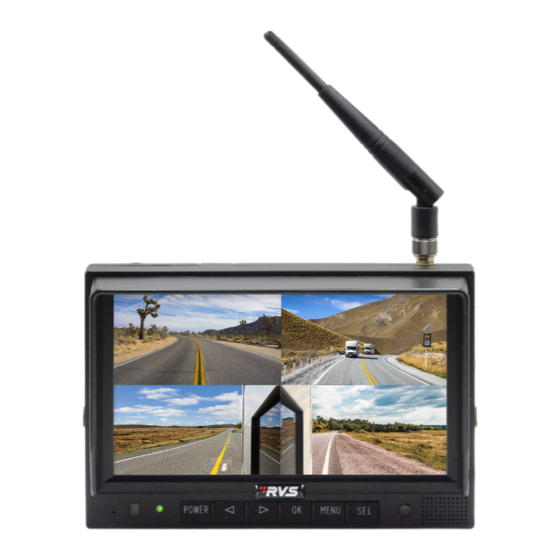
2. FEATURES AND SPECIFICATIONS 1. 7’’ HD quad-view monitor and resolution is 1024 x 600. 2. It supports three wired HD camera inputs + 1 wireless camera input and supports multiple view displays. 3. Multiple video formats available: 1080P30/1080P25/720P30/720P25/PAL/NTSC. 4. Single, dual, triplex, quad, trefoil, Y-split, and PIP view display modes are available. -
Page 10: Accessories
4. ACCESSORIES SPECIAL NOTICE: Accessory supply may be different for different applications. Rear View Safety, 1797 Atlantic Ave., Brooklyn NY 11233 800.764.1028 sales@rearviewsafety.com www.rearviewsafety.com... -
Page 11: Parts Identification
5. PARTS IDENTIFICATION Digital Color LCD Screen Power Indicator Remote Control Menu Sensor Light Sensor Single Split: The screen will be enlarged. Loudspeaker Power Switch Press OK button to switch to split mode. Volume Up Press OK button under Menu to enter Menu options. -
Page 12: Menu Operation & Functional Specification
6. MENU OPERATION & FUNCTIONAL SPECIFICATION 6.1 REMOTE CONTROL Press to select MUTE Enter/exit the standby or enable sound Exit to the main menu or Move up the menu cursor return to the previous menu Move up the menu cursor Move up the menu cur- or increase volume sor or decrease volume... - Page 13 • UP: Switch the channel without auto scan and trigger function turned on; Move the red box in the magnified mode; Move the displayed place of the magnified image. • DOWN: Switch the channel without special mode such as auto scan and trigger function turned on; Move the red box in the magnified mode;...
-
Page 14: Menu Operation
6.2 MENU OPERATION 6.2.1 DESKTOP Touch Screen Instructions: • Click the area in the red box as the pic above to open home menu. • Without special mode such as auto scan or trigger function turned on, the swiping to the left and right of the touch screen can switch the display mode following the order: CAM1->CAM2->CAM3- >CAM4->DUAL->TRIPLE->TREFOIL->Y-SPLIT->H.SPLIT->QUAD->PIP1->PIP2->PIP3->SP->CAM1. - Page 15 • Without special mode such as auto scan or trigger function turned on, and when in split view display (not PIP1/2/3 or SP), single touch one of the channel to enter single view display of the channel, and touch again to enter split view. •...
-
Page 16: Home Menu
6.2.2 HOME MENU Touch Screen Instructions: • Click the icon to enter the corresponding menu. Click the area outside the white box to exit home menu. 6.2.3 VOLUME Touch Screen Instructions: • Touch and drag the volume scroll bar to adjust the volume. •... -
Page 17: Brightness
6.2.4 BRIGHTNESS When auto dim is off: When auto dim is on: Touch Screen Instructions: • Drag the brightness scroll bar to adjust the brightness. Other Instructions: : Brightness in the day. : Brightness at night. 6.2.5 MODE Touch Screen Instructions: •... -
Page 18: Split Setup
6.2.5.1 SPLIT SETUP Touch Screen Instructions: • Click Layer 1-4/Audio icon to switch the page. • When setting up Layer 1-4: click the bottom setting to adjust the position and size of the screen display or whether to turn on this layer. •... -
Page 19: Cvbs Mode
6.2.6 CVBS MODE Touch Screen Instructions: • Click the icon to switch to the output display mode of the cvbs; • Click the area outside the menu to exit. Remote Instructions: • UP / DOWN: Cursor switch. • SEL: Select the camera channel and audio output channel. 6.2.7 SETTING Touch Screen Instructions: •... -
Page 20: Camera
6.2.7.1 CAMERA Touch Screen Instructions: • Click the camera channel icons on the top to show the parameters of the corresponding channel. • Click the ON/OFF icons or drag the scroll bars to change the features. • Click the icon to edit the camera channel name. -
Page 21: Keyboard (Show Up When Editing Channel Name)
6.2.7.1.1 KEYBOARD (APPEARS WHEN EDITING CHANNEL NAME) Touch Screen Instructions: • Click the letter icons to edit the channel name. • Clicking the letter edit box can move the cursor and change the cursor position Remote Instructions: • MODE: Switch the keyboard mode, low-case letters->special numerical character 1->special numerical character 2->capital letters->low-case letters. -
Page 22: Parking Line
6.2.7.2 PARKING LINE Touch Screen Instructions: • Click the ON/OFF/AUTO icons to select the display methods of parking lines: AUTO (display when triggered) / ON (constantly on) / OFF. Click the icon to enter parking lines calibration menu “Calibrate”. Remote Instructions: LANG: Switch system language. -
Page 23: Language
• Tapping the icon on the top left will pop up the reset icon and tap it to resume the default config. Tap TYPE1/2 icon on the top right to switch the parking line types. Tap GRID icon to turn on/off the adjustment assistance grids. -
Page 24: Trigger
6.2.7.4 TRIGGER Touch Screen Instructions: • Touch any of “Delay” line to activate digital input box; Touch any of “Priority” line to activate digital selection box. Touch any of “Display” line to activate interface to select display images. IR Instructions: •... -
Page 25: Input Panel
6.2.7.4.1 INPUT PANEL Touch Screen Instructions: • Touch the icons to edit the value. Settings will return back to previous menu without saving if touch beyond the panel. Other Instructions: • Input number will turn to 60 if larger than 60. •... -
Page 26: Auto Scan
6.2.7.4.3 DISPLAY Touch Screen Instructions: • Touch to select preferred image icon and return to previous menu by touching icon 6.2.7.5 AUTO SCAN Touch Screen Instructions: • Touch any of “Delay” line to activate digital input box. Touch Enable to turn on/off auto scan function •... -
Page 27: Power On
Feature Instructions: • Display: to set preferred display image when in auto scanning. • Delay: To set duration time of scanning image, ranging 0-60s. If delay of certain channel is set to 0, then auto scan will skip to another channel whose delay is longer than 0 second. Operation of the delay keypad is same as section 6.2.7.4.1 “Input panel. -
Page 28: Standard
6.2.7.7 STANDARD When "Automatic" is on, the monitor will automatically adjust for input cameras. If "Automatic" is off, the monitor will configure with user settings. User is able to set input formats of corresponding cameras via touching icon for each channel or turn on "Automatic" to enter automatic configuration. There will be progressing of automatic configuration, and it will display information of recognized camera after 100% finished. - Page 29 6.2.7.7.1 FORMAT MENU While using Remote Control or Button Panel, the operation includes 2 selection phases. • Phase 1 Type: If PAL or NTSC is selected, system won’t enter phase 2. • Phase 2 Resolution selection: If user enters this interface from “Standard” menu, it enters phase 1 by default.
-
Page 30: System
6.2.7.8 SYSTEM Touch Instructions: • Drag scroll bar of Dimmer to adjust screen backlight under day mode. When Auto of Dimmer is ON, backlight adjustment of Day/Night mode will be accessible by touching icon. Remote Instructions: • LANG: Switch system language. Feature Instructions: •... -
Page 31: Auto Dimmer
6.2.7.8.1 AUTO DIMMER Touch Instructions: • Drag scroll bar to adjust backlight of screen in corresponding Day/Night mode. IR Instructions: • LANG: Switch system language. Feature Instructions: • Day: Backlight degree of Day mode is always higher than that of Night mode, ranging from 0 - 60. •... -
Page 32: Wireless Channel Connection And Display
7.WIRELESS CHANNEL CONNECTION AND DISPLAY 7.1 WIRELESS CHANNEL CONNECTION DC/12V Red wire to positive power supply of DC/10~32V. Black wire to Ground. Connect the camera and display to the same DC power supply to achieve pairing. Connect Camera Rear View Safety, 1797 Atlantic Ave., Brooklyn NY 11233 800.764.1028 sales@rearviewsafety.com www.rearviewsafety.com... - Page 33 1 2 3 4 5 6 7 Cam 2 Cam 3 Cam 4 CVBS Air Vue™ Wireless Optional Transmitter Backup Camera 5-Pin Female 5-Pin Male 2-Pin Power Connector Power RVS-TPA5 Rear View Safety, 1797 Atlantic Ave., Brooklyn NY 11233 800.764.1028 sales@rearviewsafety.com www.rearviewsafety.com...
-
Page 34: Wireless Channel Display
7.2 WIRELESS CHANNEL DISPLAY When not paired, Channel 1 will always display the corresponding prompt information. After the pairing is successful, the paired prompt will be displayed for a short time and the prompt will disappear automatically. Rear View Safety, 1797 Atlantic Ave., Brooklyn NY 11233 800.764.1028 sales@rearviewsafety.com www.rearviewsafety.com... -
Page 35: Troubleshooting
8. TROUBLESHOOTING Solutions for poor transmitter signal 1. Please confirm the antennas of the display and on the transmitter are perpendicular to the ground, and the antennas are tightened. 2. If there is metal shielding between the monitor and the camera, an extended antenna should be used to bypass the metal shielding to ensure smooth transmission of antenna signal in space. -
Page 36: Warranty
ONE YEAR WARRANTY REAR VIEW SAFETY, INC. WARRANTS THIS PRODUCT AGAINST MATERIAL DEFECTS FOR A PERIOD OF ONE YEAR FROM DATE OF PURCHASE. WE RESERVE THE RIGHT TO REPAIR OR REPLACE ANY SUCH DEFECTIVE UNIT AT OUR SOLE DISCRETION. REAR VIEW SAFETY, INC. IS NOT RESPONSIBLE FOR A DEFECT IN THE SYSTEM AS A RESULT OF MISUSE, IMPROPER INSTALLATION, DAMAGE OR MISHANDLING OF THE ELECTRONIC COMPONENTS. -
Page 37: Disclaimer
DISCLAIMER REAR VIEW SAFETY AND/OR ITS AFFILIATES DOES NOT GUARANTEE OR PROMISE THAT THE USER OF OUR SYSTEMS WILL NOT BE IN/PART OF AN ACCIDENT OR OTHERWISE NOT COLLIDE WITH AN OBJECT AND/OR PERSON. OUR SYSTEMS ARE NOT A SUBSTITUTE FOR CAREFUL AND CAUTIOUS DRIVING OR FOR THE CONSISTENT ADHERENCE TO ALL APPLICABLE TRAFFIC LAWS AND MOTOR VEHICLE SAFETY REGULATIONS. - Page 38 Engineered For Vehicle Safety If you have questions about this product, please contact us at: 800.764.1028 sales@rearviewsafety.com www.rearviewsafety.com New York 1797 Atlantic Ave Brooklyn, NY 11233 Indiana 319 Roske Dr. Elkhart, Indiana 46516 Canada 68 Trafalgar Square Thornhill, ON, L4J 7M5, Canada...
Need help?
Do you have a question about the AIR VUE RVS-7MCM and is the answer not in the manual?
Questions and answers