MSI PRO B650-P WIFI User Manual
Hide thumbs
Also See for PRO B650-P WIFI:
- User manual (444 pages) ,
- User manual (66 pages) ,
- User manual
Table of Contents
Advertisement
Quick Links
Advertisement
Table of Contents

Related Manuals for MSI PRO B650-P WIFI


Summary of Contents for MSI PRO B650-P WIFI
- Page 1 PRO B650-P WIFI Motherboard User Guide...
-
Page 2: Table Of Contents
Contents Quick Start ........................3 Specifications ......................17 Special Features ....................... 21 Package Contents ..................... 22 Back Panel Connectors ..................... 23 LAN Port LED Status Table ....................24 Audio Jacks Connection ..................... 24 Installing Antennas ......................26 Overview of Components ..................27 CPU Socket ........................ - Page 3 Installing OS, Drivers & MSI Center ................46 Installing Drivers with MSI Driver Utility Installer.............. 47 MSI Center ........................48 UEFI BIOS ......................... 50 BIOS Setup ........................51 Resetting BIOS ........................52 Updating BIOS ........................52...
-
Page 4: Quick Start
Quick Start Thank you for purchasing a new motherboard from MSI®. This Quick Start section provides demonstration diagrams about how to install your computer. Some of the installations also provide video demonstrations. Please link to the URL to watch it with the web browser on your phone or tablet. - Page 5 Safety Information ∙ The components included in this package are prone to damage from electrostatic discharge (ESD). Please adhere to the following instructions to ensure successful computer assembly. ∙ Ensure that all components are securely connected. Loose connections may cause the computer to not recognize a component or fail to start.
- Page 8 ⚠ Important If you are installing the screw-type CPU heatsink, please follow the figure below to remove the retention module first and then install the heatsink.
- Page 9 Installing DDR5 memory ⚽ ∙ https://youtu.be/XiNmkDNZcZk...
- Page 11 Connecting the Front Panel Header...
- Page 13 Connecting the Power Connectors ⚽...
- Page 16 Connecting Peripheral Devices...
-
Page 18: Specifications
Specifications ∙ Supports AMD Ryzen™ 7000 Series Desktop Processor* ∙ Processor socket AM5 * Please go to www.msi.com to get the newest support status as new processors are released. Chipset AMD B650 Chipset ∙ 4x DDR5 memory slots, supporting up to 192GB* ∙... - Page 19 Continued from previous column ∙ 6x SATA 6Gb/s ports • SATA_1~2 (From B650 chipset) SATA Ports • SATA_A1~A4 (From ASM1064) ∙ 2x M.2 slots (Key M) • M2_1 slot (From CPU) • Supports up to PCIe 4.0 x4 • Supports 2280/ 22110 storage devices M.2 SSD Slots •...
- Page 20 Continued from previous column ∙ 1x 24-pin ATX main power connector Power Connectors ∙ 2x 8-pin +12V power connectors ∙ 1x USB 3.2 Gen 2 10Gbps Type-C front panel port (From B650 chipset) ∙ 1x USB 3.2 Gen 1 5Gbps connector (From B650 chipset) Internal USB •...
- Page 21 ∙ 9.6 in. x 12.0 in. (244 mm x 305 mm) ∙ 1x 256 Mb flash ∙ UEFI AMI BIOS ∙ ACPI 6.4, SMBIOS 3.5 BIOS Features ∙ Multi-language ∙ Drivers ∙ MSI Center ∙ CPU-Z MSI GAMING Software ∙ Norton 360 Deluxe ∙ AIDA64 Extreme - MSI Edition...
-
Page 22: Special Features
• Hardware Monitoring BIOS • Super Charger • Click BIOS 5 • Devices Speed Up • Smart Image Finder • MSI Companion • System Diagnosis • Smart Fan Control Thermal Features • Extended Heatsink Design • M.2 Shield Frozr • K7 MOSFET thermal pad / Extra choke pad •... -
Page 23: Package Contents
Package Contents Please check the contents of your motherboard package. It should contain: Board • 1x Motherboard Documentation • 1x Quick installation guide • 1x European Union regulatory notice Cables • 1x SATA6Gb/s cable Accessories • 1x Wi-Fi antenna set •... -
Page 24: Audio Jacks Connection
USB 3.2 Gen 1 5Gbps Type-A ports (From Hub-1074) Wi-Fi antenna connectors Audio jacks HDMI™ port USB 3.2 Gen 2 10Gbps Type-A port (From CPU) ∙ Flash BIOS Port USB 3.2 Gen 2 10Gbps Type-A port (From CPU)) USB 3.2 Gen 2x2 20Gbps Type-C port (From B650 chipset) LAN Port LED Status Table Audio Jacks Connection Audio jacks to headphone and microphone diagram... -
Page 25: Installing Antennas
Audio jacks to stereo speakers diagram Audio jacks to 4-channel speakers diagram Audio jacks to 5.1-channel speakers diagram Audio jacks to 7.1-channel speakers diagram Installing Antennas 1. Screw the antennas tight to the antenna connectors as shown below. 2. Orient the antennas. -
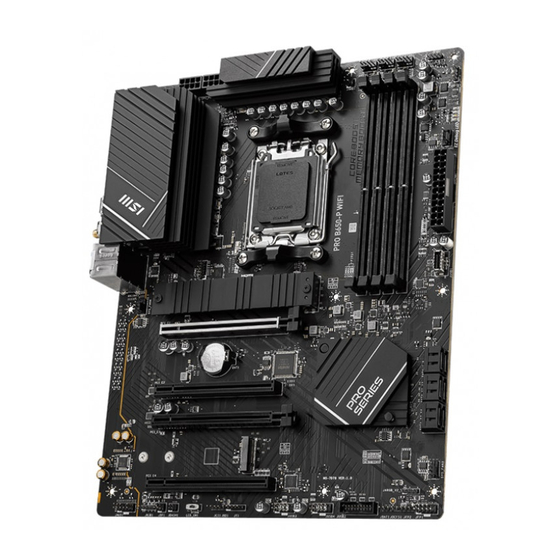
Page 27: Overview Of Components
Overview of Components... -
Page 28: Cpu Socket
This motherboard is designed to support overclocking. Before attempting to overclock, please make sure that all other system components can tolerate overclocking. Any attempt to operate beyond product specifications is not recommended. MSI® does not guarantee the damages or risks caused by inadequate operation beyond product specifications. -
Page 29: Pci_E1~4: Pcie Expansion Slots
∙ If you install a large and heavy graphics card, you need to use a tool such as MSI Graphics Card Bolster to support its weight to prevent deformation of the slot. ∙ For a single PCIe x16 expansion card installation with optimum performance, using the PCI_E1 slot is recommended. - Page 30 if you install 22110 SSD. Insert your M.2 SSD into the M.2 slot at a 30-degree angle. Rotate the EZ M.2 Clip to fix the M.2 SSD. 6. Remove the protective films from the thermal pads under the M.2 Shield Frozr heatsink. 7.
- Page 31 Installing M.2 module into M2_2 slot 1. Install the supplied EZ M.2 Clip kit in the M.2 slot according to your SSD length. 2. Insert your M.2 SSD into the M.2 slot at a 30-degree angle. 3. Rotate the EZ M.2 Clip to fix the M.2 SSD.
-
Page 32: Sata_1~2, Sata_A1~A4: Sata 6Gb/S Connectors
SATA_1~2, SATA_A1~A4: SATA 6Gb/s Connectors These connectors are SATA 6Gb/s interface ports. Each connector can connect to one SATA device. ∙ Please do not fold the SATA cable at a 90-degree angle. Data loss may result during transmission otherwise. ∙ SATA cables have identical plugs on either sides of the cable. -
Page 33: Jci1: Chassis Intrusion Connector
Signal Name Signal Name Ground Ground Ground Ground +12V +12V CPU_PWR1~2 +12V +12V ATX_PWR1 Signal Name Signal Name +3.3V +3.3V Ground Ground Ground PWR OK CPU_PWR1~2 4851 5VSB +12V +12V +3.3V ATX_PWR1 +3.3V -12V Ground PS-ON# Ground Ground Ground Ground ⚠... -
Page 34: Jusb1: Usb 3.2 Gen 2 10Gbps Type-C Front Panel Connector
1. Go to BIOS > SETTINGS > Security > Chassis Intrusion Configuration. 2. Set Chassis Intrusion to Reset. 3. Press F10 to save and exit and then press the Enter key to select Yes. JUSB1: USB 3.2 Gen 2 10Gbps Type-C front panel Connector This connector allows you to connect USB Type-C connector on the front panel. -
Page 35: Jtpm1: Tpm Module Connector
∙ In order to recharge your iPad, iPhone and iPod through USB ports, please install MSI Center utility. JTPM1: TPM Module Connector This connector is for TPM (Trusted Platform Module). Please refer to the TPM security platform manual for more details and usages. - Page 36 1211 Reserved No Pin Reserved Interrupt Request CPU_FAN1, PUMP_FAN1, SYS_FAN1~4: Fan Connectors Fan connectors can be classified as PWM (Pulse Width Modulation) Mode or DC Mode. PWM Mode fan connectors provide constant 12V output and adjust fan speed with speed control signal. DC Mode fan connectors control fan speed by changing voltage.
-
Page 37: Jbat1: Clear Cmos (Reset Bios) Jumper
JBAT1: Clear CMOS (Reset BIOS) Jumper There is CMOS memory onboard that is external powered from a battery located on the motherboard to save system configuration data. If you want to clear the system configuration, set the jumpers to clear the CMOS memory. -
Page 38: Jargb_V2_1~2: A-Rainbow V2 (Argb Gen2) Led Connectors
Always turn off the power supply and unplug the power cord from the power outlet before installing or removing the RGB LED strip. ∙ Please use MSI’s software to control the extended LED strip. JARGB_V2_1~2: A-RAINBOW V2 (ARGB Gen2) LED connectors The JARGB_V2 connectors allow you to connect the ARGB Gen2 and the ARGB-based LED strips. - Page 39 It is recommended that you install LED strips with the same specification to achieve the best effects. ∙ Always turn off the power supply and unplug the power cord from the power outlet before installing or removing the addressable RGB LED strip. ∙ Please use MSI’s software to control the extended LED strip.
-
Page 40: Jocfs1: Safe Boot Jumper
LED_SW1 Installing OS, Drivers & MSI Center Please download and update the latest utilities and drivers at www.msi.com Installing Windows 10/ Windows 11 1. Power on the computer. 2. Insert the Windows 10/ Windows 11 installation disc/USB into your computer. -
Page 41: Installing Drivers With Msi Driver Utility Installer
∙ The MSI Driver Utility Installer will only pop up once. If you cancel or close it during the process, please refer to the Live Update chapter of the MSI Center manual to install the drivers. You can also go to www.msi.com to search your motherboard and download the drivers. -
Page 42: Msi Center
MSI Center MSI Center is an application that helps you easily optimize game settings and smoothly use content creation softwares. It also allows you to control and synchronize LED light effects on PCs and other MSI products. With MSI Center, you can customize ideal modes, monitor system performance, and adjust fan speed. -
Page 43: Uefi Bios
MSI UEFI BIOS is compatible with UEFI (Unified Extensible Firmware Interface) architecture. UEFI has many new functions and advantages that traditional BIOS cannot achieve, and it will completely replace BIOS in the future. The MSI UEFI BIOS uses UEFI as the default boot mode to take full advantage of the new chipset’s capabilities. -
Page 44: Resetting Bios
Be sure the computer is off before clearing CMOS data. Please refer to the Clear CMOS jumper section for resetting BIOS. Updating BIOS Updating BIOS with M-FLASH Before updating: Please download the latest BIOS file that matches your motherboard model from MSI website. And then save the BIOS file into the USB flash drive. Updating BIOS: 1. - Page 45 3. Connect the power supply to CPU_PWR1 and ATX_PWR1. (No need to install CPU and memory.) 4. Plug the USB storage device that contains the MSI.ROM file into the Flash BIOS Port on the rear I/O panel. 5. Press the Flash BIOS Button to update BIOS, and the LED starts flashing.
Need help?
Do you have a question about the PRO B650-P WIFI and is the answer not in the manual?
Questions and answers