
Subscribe to Our Youtube Channel
Related Manuals for MSI PRO B660M-A CEC WIFI DDR4 V2


Summary of Contents for MSI PRO B660M-A CEC WIFI DDR4 V2
- Page 1 PRO B660M-A CEC WIFI DDR4 V2 Motherboard User Guide Benutzerhandbuch Manuel d’utilisation Руководство пользователя 取扱説明書 사용 명서 使用手冊 使用手册...
- Page 2 English Deutsch Français Русский 日本語 한국어 繁體中文 简体中文...
-
Page 3: Table Of Contents
JCOM1: Serial Port Connector .................22 JRGB1: RGB LED connector ..................22 JRAINBOW1~2: Addressable RGB LED connectors ..........23 EZ Debug LED ......................23 Installing OS, Drivers & MSI Center .............. 24 Installing Windows 10/ Windows 11 .................24 Installing Drivers ......................24 MSI Center ........................24... - Page 4 UEFI BIOS ....................... 25 BIOS Setup ........................26 Entering BIOS Setup ....................26 BIOS User Guide .......................26 Resetting BIOS ......................27 Updating BIOS......................27 Contents...
-
Page 5: Safety Information
Safety Information ∙ The components included in this package are prone to damage from electrostatic discharge (ESD). Please adhere to the following instructions to ensure successful computer assembly. ∙ Ensure that all components are securely connected. Loose connections may cause the computer to not recognize a component or fail to start. -
Page 6: Specifications
Supports 12th/ 13th Gen Intel® Core™ Processors, Pentium® Gold and Celeron® Processors* ∙ Processor socket LGA1700 * Please go to www.msi.com to get the newest support status as new processors are released. Chipset Intel® B660 chipset 4x DDR4 memory slots, support up to 128GB* ∙... - Page 7 Continued from previous page ∙ Intel® Wi-Fi 6E ∙ The Wireless module is pre-installed in the M.2 (Key-E)slot ∙ Supports MU-MIMO TX/RX, 2.4GHz/ 5GHz/ 6GHz*(160MHz)up to 2.4Gbps Wireless LAN & ∙ Supports 802.11 a/ b/ g/ n/ ac/ ax Bluetooth® ∙...
- Page 8 Continued from previous page ∙ Intel® B660 Chipset ▪ 2x USB 3.2 Gen 2 10Gbps (Type-A+Type-C) ports on the back panel ▪ 3x USB 3.2 Gen 1 5Gbps ports (2 Type-A ports and 1 Type-C port available through the internal USB connectors) ▪...
- Page 9 BIOS Features ∙ ACPI 6.4, SMBIOS 3.4 ∙ Multi-language ∙ Drivers MSI Center ∙ ∙ Intel® Extreme Tuning Utility Software ∙ CPU-Z MSI GAMING ∙ Google Chrome™, Google Toolbar, Google Drive ∙ Norton™ Internet Security Solution Continued on next page Specifications...
- Page 10 ∙ LAN Manager ∙ Mystic Light ∙ Ambient Devices ∙ Frozr AI Cooling ∙ User Scenario ∙ True Color MSI Center Features ∙ Live Update ∙ Hardware Monitoring ∙ Super Charger ∙ Speed Up ∙ Smart Image Finder ∙ MSI Companion ∙...
- Page 11 Dual CPU Power Special Features ▪ 2oz Copper thickened PCB ∙ Protection ▪ PCI-E Steel Armor ∙ Experience ▪ MSI Center ▪ Click BIOS 5 ▪ Forzr AI Cooling ▪ CPU Cooler Tuning ▪ EZ DEBUG LED ▪ App Player Tile ▪...
-
Page 12: Rear I/O Panel
Rear I/O Panel Line-out PS/2 Combo port Line-in Wi-Fi Antenna 2.5 Gbps LAN connectors USB 3.2 Gen 1 5Gbps Type-A USB 3.2 Gen 2 USB 2.0 Type-A Mic-in 10Gbps Type-A USB 3.2 Gen 2 10Gbps Type-C LAN Port LED Status Table Link/ Activity LED Speed LED Status... -
Page 13: Overview Of Components
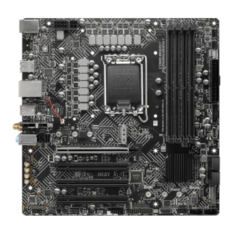
Overview of Components DIMMA1 Processor Socket DIMMA2 CPU_PWR2 CPU_FAN1 DIMMB1 CPU_PWR1 DIMMB2 JRAINBOW1 PUMP_FAN1 SYS_FAN1 ATX_PWR1 52mm* M2_1 JUSB3 SYS_FAN2 JUSB4 PCI_E1 SATA▼5▲6 PCI_E2 SATA▼7▲8 PCI_E3 M2_2 PCI_E4 JCI1 JFP2 JAUD1 JRGB1 SATA_A1 JDASH1 SATA_B1 JRAINBOW2 JFP1 JUSB1 JTPM1 JUSB2 JCOM1 JBAT1 JLPT1... -
Page 14: Cpu Socket
Always unplug the power cord from the power outlet before installing or removing ∙ the CPU. ∙ Please retain the CPU protective cap after installing the processor. MSI will deal with Return Merchandise Authorization (RMA) requests if only the motherboard comes with the protective cap on the CPU socket. ∙... -
Page 15: Dimm Slots
DIMM Slots Please install the memory module into the DIMM slot as shown below. Memory module installation recommendation DIMMA2 DIMMA2 DIMMB2 DIMMA1 DIMMA2 DIMMB1 DIMMB2 Overview of Components... -
Page 16: Pci_E1~4: Pcie Expansion Slots
If you install a large and heavy graphics card, you need to use a tool such as MSI ∙ Gaming Series Graphics Card Bolster to support its weight to prevent deformation of the slot. -
Page 17: Jfp1, Jfp2: Front Panel Connectors
JFP1, JFP2: Front Panel Connectors These connectors connect to the switches and LEDs on the front panel. HDD LED + Power LED + Power LED Power Switch HDD LED - Power LED - Reset Switch Power Switch Reserved Reset Switch Power Switch HDD LED Reset Switch... -
Page 18: Sata5~8, Sata_A1& Sata_B1: Sata 6Gb/S Connectors
SATA5~8, SATA_A1& SATA_B1: SATA 6Gb/s Connectors These connectors are SATA 6Gb/s interface ports. Each connector can connect to one SATA device. SATA6 SATA5 SATA8 SATA7 SATA_B1 SATA_A1 ⚠ Important SATA7 will be unavailable when installing M.2 SATA SSD in the M2_2 slot. ∙... -
Page 19: Atx_Pwr1, Cpu_Pwr1~2: Power Connectors
ATX_PWR1, CPU_PWR1~2: Power Connectors These connectors allow you to connect an ATX power supply. +3.3V +3.3V +3.3V -12V Ground Ground PS-ON# Ground Ground Ground ATX_PWR1 Ground Ground PWR OK 5VSB +12V +12V +3.3V Ground Ground +12V Ground +12V CPU_PWR1 Ground +12V Ground +12V... -
Page 20: Jusb1~2: Usb 2.0 Connectors
In order to recharge your iPad,iPhone and iPod through USB ports, please install ∙ MSI Center utility. JUSB3: USB 3.2 Gen 1 Connector This connector allows you to connect USB 3.2 Gen 1 5Gbps ports on the front panel. -
Page 21: Jusb4: Usb 3.2 Gen 1 Type-C Connector
JUSB4: USB 3.2 Gen 1 Type-C Connector This connector allows you to connect USB 3.2 Gen 1 5Gbps Type-C connector on the front panel. The connector possesses a foolproof design. When you connect the cable, be sure to connect it with the corresponding orientation. JUSB4 USB Type-C Cable USB Type-C port on the... -
Page 22: Cpu_Fan1, Pump_Fan1, Sys_Fan1~2: Fan Connectors
CPU_FAN1, PUMP_FAN1, SYS_FAN1~2: Fan Connectors Fan connectors can be classified as PWM (Pulse Width Modulation) Mode or DC Mode. PWM Mode fan connectors provide constant 12V output and adjust fan speed with speed control signal. DC Mode fan connectors control fan speed by changing voltage. -
Page 23: Jci1: Chassis Intrusion Connector
JCI1: Chassis Intrusion Connector This connector allows you to connect the chassis intrusion switch cable. Normal Trigger the chassis (default) intrusion event Using chassis intrusion detector Connect the JCI1 connector to the chassis intrusion switch/ sensor on the chassis. Close the chassis cover. Go to BIOS >... -
Page 24: Jbat1: Clear Cmos (Reset Bios) Jumper
(12V/G/R/B) with the maximum power rating of 3A (12V). ∙ Always turn off the power supply and unplug the power cord from the power outlet before installing or removing the RGB LED strip. Please use MSI’s software to control the extended LED strip. ∙ Overview of Components... -
Page 25: Jrainbow1~2: Addressable Rgb Led Connectors
∙ before installing or removing the RGB LED strip. ∙ Please use MSI’s software to control the extended LED strip. EZ Debug LED These LEDs indicate the status of the motherboard. CPU - indicates CPU is not detected or fail. -
Page 26: Installing Os, Drivers & Msi Center
MSI Center is an application that helps you easily optimize game settings and smoothly use content creation softwares. It also allows you to control and synchronize LED light effects on PCs and other MSI products. With MSI Center, you can customize ideal modes, monitor system performance, and adjust fan speed. -
Page 27: Uefi Bios
UEFI has many new functions and advantages that traditional BIOS cannot achieve, and it will completely replace BIOS in the future. The MSI UEFI BIOS uses UEFI as the default boot mode to take full advantage of the new chipset’s capabilities. -
Page 28: Bios Setup
* When you press F10, a confirmation window appears and it provides the modification information. Select between Yes or No to confirm your choice. BIOS User Guide If you’d like to know more instructions on setting up the BIOS, please refer to http://download.msi.com/manual/mb/Intel600BIOS.pdf or scan the QR code to access. UEFI BIOS... -
Page 29: Resetting Bios
Updating BIOS Updating BIOS with M-FLASH Before updating: Please download the latest BIOS file that matches your motherboard model from MSI website. And then save the BIOS file into the USB flash drive. Updating BIOS: Insert the USB flash drive that contains the update file into the USB port. - Page 30 Please close all other application software before updating the BIOS. ∙ To update BIOS: Install and launch MSI Center and go to Support page. Select Live Update and click on Advance button. Select the BIOS file and click on Install button.
- Page 31 JCOM1: Serieller Anschluss ..................22 JRGB1: RGB LED Anschluss ..................22 JRAINBOW1~2: Adressierbarer RGB-LED-Streifen Anschlüsse ......23 EZ DEBUG LED ......................23 Installation von OS, Treibern & MSI Center ......... 24 Installation von Windows 10/ Windows 11 ...............24 Installation von Treibern ..................24 MSI Center ........................25...
- Page 32 UEFI BIOS .................... 26 BIOS Setup ........................27 Öffnen des BIOS Setups ...................27 BIOS-Benutzerhandbuch ..................27 Reset des BIOS ......................28 Aktualisierung des BIOS...................28 Inhalt...
-
Page 33: Sicherheitshinweis
Sicherheitshinweis ∙ Die im Paket enthaltene Komponenten sind der Beschädigung durch elektrostatischen Entladung (ESD). Beachten Sie bitte die folgenden Hinweise, um die erfolgreichen Computermontage sicherzustellen. ∙ Stellen Sie sicher, dass alle Komponenten fest angeschlossen sind. Lockere Steckverbindungen können Probleme verursachen, zum Beispiel: Der Computer erkennt eine Komponente nicht oder startet nicht. -
Page 34: Spezifikationen
Spezifikationen ∙ Unterstützt Intel® Core™ der 12./13. Generation Prozessoren, Pentium® Gold und Celeron® Prozessoren ∙ Prozessor Sockel LGA1700 * Bitte besuchen Sie www.msi.com, um den neuesten Support-Status zu erhalten, wenn neue Prozessoren veröffentlicht werden. Chipsatz Intel® B660 Chipsatz ∙ 4x DDR4 Speicherplätze, aufrüstbar bis 128 GB* ∙... - Page 35 Fortsetzung der vorherigen Seite Intel® Wi-Fi 6E ∙ Das Wireless-Modul ist im M.2 (Key-E) Steckplatz vorinstalliert ∙ Unterstützt MU-MIMO TX/RX, 2,4GHz/ 5GHz/ 6GHz* (160MHz) mit Datenraten bis zu 2,4Gbit/s ∙ Unterstützt 802.11 a/ b/ g/ n/ ac/ ax Wireless LAN & Bluetooth®...
- Page 36 Fortsetzung der vorherigen Seite ∙ Intel® B660 Chipsatz ▪ 2x USB 3.2 Gen 2 10Gbit/s (Type-A+Type-C) Anschlüsse an der rückseitigen Anschlussleiste ▪ 3x USB 3.2 Gen 1 5Gbit/s Anschlüsse (2 Typ-A Anschlüsse an der rückseitigen Anschlussleiste und 1 Anschlüsse stehen durch die internen Anschlüsse zur Verfügung) ▪...
- Page 37 ∙ ACPI 6.4, SMBIOS 3.4 ∙ Mehrsprachenunterstützung ∙ Treiber ∙ MSI Center ∙ Intel® Extreme Tuning Utility Software ∙ CPU-Z MSI GAMING ∙ Google Chrome™, Google Toolbar, Google Drive ∙ Norton™ Internet Security Solution Fortsetzung auf der nächsten Seite Spezifikationen...
- Page 38 Fortsetzung der vorherigen Seite ∙ LAN Manager ∙ Mystic Light ∙ Umgebungsgeräte ∙ Frozr AI Kühlung ∙ Benutzer-Szenario ∙ True Color MSI Center Funktionen ∙ Live Update ∙ Hardware Monitor ∙ Super Charger ∙ Speed Up ∙ Smart Image Finder ∙...
- Page 39 ▪ Dual-CPU-Power Besondere Funktionen ▪ 2oz Kupfer verdicktes PCB ∙ Schutz ▪ PCI-E Steel Armor ∙ Erfahrung ▪ MSI Center ▪ Click BIOS 5 ▪ Frozr AI Kühlung ▪ CPU Cooler Tuning ▪ EZ DEBUG LED ▪ App-Player Tile ▪...
-
Page 40: Rückseite E/A
Rückseite E/A Line-Out PS/2 Combo-Anschluss Line-In Wi-Fi Antennen- 2,5 Gbit/s LAN anschlüsse USB 3.2 Gen 1 5Gbit/s Typ-A USB 3.2 Gen 2 USB 2.0 Typ-A Mic-In 10Gbit/s Typ-A USB 3.2 Gen 2 (10Gbit/s) Typ-C LAN Port LED Zustandstabelle Verbindung/ Aktivität LED Geschwindigkeit LED Zustand Bezeichnung... -
Page 41: Übersicht Der Komponenten
Übersicht der Komponenten DIMMA1 Prozessor Sockel DIMMA2 CPU_PWR2 CPU_FAN1 DIMMB1 CPU_PWR1 DIMMB2 JRAINBOW1 PUMP_FAN1 SYS_FAN1 ATX_PWR1 52mm* M2_1 JUSB3 SYS_FAN2 JUSB4 PCI_E1 SATA▼5▲6 PCI_E2 SATA▼7▲8 PCI_E3 M2_2 PCI_E4 JCI1 JFP2 JAUD1 JRGB1 SATA_A JDASH1 SATA_B JRAINBOW2 JFP1 JUSB1 JTPM1 JUSB2 JCOM1 JBAT1 JLPT1... -
Page 42: Cpu Sockel
Bitte bewahren Sie die CPU Schutzkappe nach der Installation des Prozessors auf. ∙ MSI wird RMA (Return Merchandise Authorization) Anfragen nur dann behandeln, wenn die Schutzklappe auf dem CPU-Sockel des Motherboards sitzt. Wenn Sie eine CPU einbauen, denken sie bitte daran, einen CPU-Kühler zu instal- ∙... -
Page 43: Dimm Steckplätze
DIMM Steckplätze Setzen Sie bitte ein Speichermodul wie untern gezeigt in den DIMM-Steckplatz ein. Speichermodul-Installationsempfehlung DIMMA2 DIMMA2 DIMMB2 DIMMA1 DIMMA2 DIMMB1 DIMMB2 Übersicht der Komponenten... -
Page 44: Pci_E1~4: Pcie Erweiterungssteckplätze
Wenn Sie eine große und schwere Grafikkarte einbauen, benötigen Sie einen ∙ Grafikkarten-Stabilisator (Graphics Card Bolster) der MSI Gaming Serien der das Gewicht trägt und eine Verformung des Steckplatzes vermeidet. Für die Installation einer einzelnen PCIe x16 Erweiterungskarte mit optimaler ∙... -
Page 45: Jfp1, Jfp2: Frontpanel-Anschlüsse
JFP1, JFP2: Frontpanel-Anschlüsse Diese Anschlüsse verbinden die Schalter und LEDs des Frontpanels. HDD LED + Power LED + Power LED Power Switch HDD LED - Power LED - Reset Switch Power Switch Reserved Reset Switch Power Switch HDD LED Reset Switch Reserved No Pin HDD LED -... -
Page 46: Sata5~8, Sata_A1& Sata_B1: Sata 6Gb/S Anschlüsse
SATA5~8, SATA_A1& SATA_B1: SATA 6Gb/s Anschlüsse Dieser Anschluss basiert auf der Hochgeschwindigkeitsschnittstelle SATA 6 Gb/s. Pro Anschluss kann ein SATA Gerät angeschlossen werden. SATA6 SATA5 SATA8 SATA7 SATA_B1 SATA_A1 ⚠ Wichtig ∙ Der SATA7 Anschluss wird nicht zur Verfügung stehen, wenn Sie eine M.2 SATA SSD im M2_2 Steckplatz installieren. -
Page 47: Atx_Pwr1, Cpu_Pwr1~2: Stromanschlüsse
ATX_PWR1, CPU_PWR1~2: Stromanschlüsse Mit diesen Anschlüssen verbinden Sie die ATX Stromstecker. +3,3V +3,3V +3,3V -12V Ground Ground PS-ON# Ground Ground Ground ATX_PWR1 Ground Ground PWR OK 5VSB +12V +12V +3,3V Ground Ground +12V Ground +12V CPU_PWR1 Ground +12V Ground +12V Ground +12V CPU_PWR2... -
Page 48: Jusb1~2: Usb 2.0 Anschlüsse
Um ein iPad, iPhone und einen iPod über USB-Anschlüsse aufzuladen, installieren ∙ Sie bitte die MSI® Center-Dienstprogramm. JUSB3: USB 3.2 Gen 1 Anschluss Mit diesem Anschluss können Sie die USB 3.2 Gen 1 5Gbit/s Anschlüsse auf dem Frontpanel verbinden. -
Page 49: Jusb4: Usb 3.2 Gen 1 Typ-C Anschluss
JUSB4: USB 3.2 Gen 1 Typ-C Anschluss Mit diesem Anschluss können Sie den USB 3.2 Gen 1 Typ-C Anschluss auf dem Frontpanel verbinden. Der Anschluss verfügt über ein besonders sicheres Design. Wenn Sie das Kabel anschließen, müssen Sie es in der entsprechenden Ausrichtung verbinden. -
Page 50: Cpu_Fan1, Pump_Fan1, Sys_Fan1~2: Stromanschlüsse Für Lüfter
CPU_FAN1, PUMP_FAN1, SYS_FAN1~2: Stromanschlüsse für Lüfter Diese Anschlüsse können im PWM (Pulse Width Modulation) Modus oder Spannungsmodus betrieben werden. Im PWM-Modus bieten die Lüfteranschlüsse konstante 12V Ausgang und regeln die Lüftergeschwindigkeit per Drehzahlsteuersignal. Im DC-Modus bestimmen die Lüfteranschlüsse die Lüftergeschwindigkeit durch Ändern der Spannung. Standard- Anschluss Max. -
Page 51: Jci1: Gehäusekontaktanschluss
JCI1: Gehäusekontaktanschluss Dieser Anschluss wird mit einem Kontaktschalter verbunden Normal Löse den Gehäuseeingriff (Standardwert) Gehäusekontakt-Detektor verwenden Schließen Sie den JCI1 -Anschluss am Gehäusekontakt-Schalter/ Sensor am Gehäuse an. Schließen Sie die Gehäuseabdeckung. Gehen Sie zu BIOS > SETTINGS > Security > Chassis Intrusion Configuration. Stellen Sie Chassis Intrusion auf Enabled. -
Page 52: Jbat1: Clear Cmos Steckbrücke (Reset Bios)
R/B) mit der maximalen Leistung von 3 A (12 V) ∙ Schalten Sie die Stromversorgung aus und ziehen Sie das Netzkabel ab, bevor Sie die RGB-LED-Streifen ein- und ausbauen. Bitte verwenden Sie die MSI-Software zur Steuerung des LED-Leuchtstreifens. ∙ Übersicht der Komponenten... -
Page 53: Jrainbow1~2: Adressierbarer Rgb-Led-Streifen Anschlüsse
Schalten Sie die Stromversorgung aus und ziehen Sie das Netzkabel ab, bevor Sie ∙ die RGB-LED-Streifen ein- und ausbauen. ∙ Bitte verwenden Sie die MSI-Software zur Steuerung des LED-Leuchtstreifens. EZ DEBUG LED Diese LEDs zeigen den Debug-Status des Motherboards an. CPU - CPU wird nicht erkannt oder ist fehlerhaft. -
Page 54: Installation Von Os, Treibern & Msi Center
Installation von Treibern Starten Sie Ihren Computer mit Windows 10/ Windows 11. Legen Sie die MSI® Treiber Disk/ USB-Treiber in das optische Laufwerk. Klicken Sie auf die Pop-up-Meldung Wählen Sie eine Aktion für Wechseldatenträger aus , und wählen Sie DVDSetup.exe starten aus, um den Installer zu öffnen. -
Page 55: Msi Center
Software zur Erstellung von Inhalten einstellen können. Außerdem können Sie LED-Lichteffekte in PCs und anderen MSI-Produkten steuern und synchronisieren. Mit MSI Center können Sie ideale Modi einstellen, die Systemleistung überwachen und die Lüftergeschwindigkeit anpassen. MSI Center Benutzerhandbuch Wenn Sie weitere Informationen zu MSI Center wünschen, besuchen... -
Page 56: Uefi Bios
UEFI BIOS Das MSI UEFI-BIOS ist mit der UEFI-Architektur (Unified Extensible Firmware Interface) kompatibel. Das UEFI-BIOS hat viele neue Funktionen und besitzt Vorteile, die das traditionelle BIOS nicht bieten kann. Es wird zukünftige PCs und Geräte, die der UEFI-Firmware-Architektur entsprechen, vollständig unterstützen. Das MSI UEFI-BIOS verwendet UEFI als Standard-Startmodus, um die Funktionen des neuen Chipsatzes voll auszunutzen. -
Page 57: Bios Setup
* Beim Drücken der F10 Taste wird das Fenster zum Speichern der Einstellungen angezeigt. Wählen Sie Yes, um die Wahl zu bestätigen, oder No, um die derzeitige Einstellung beizubehalten. BIOS-Benutzerhandbuch Wenn Sie weitere Anweisungen zur BIOS-Einrichtung wünschen, lesen Sie bitte http://download.msi.com/manual/mb/Intel600BIOSde.pdf oder scannen Sie den QR-Code. UEFI BIOS... -
Page 58: Reset Des Bios
Aktualisierung des BIOS mit dem M-FLASH-Programm Vorbereitung: Laden Sie bitte die neueste BIOS Version, die dem Motherboard-Modell entspricht, von der offiziellen MSI Website herunter. und speichern Sie die BIOS-Datei auf USB- Flash-Laufwerk. BIOS-Aktualisierungsschritte: Schließen das USB-Flashlaufwerk mit der BIOS-Datei an den Computer. - Page 59 Schritte zur Aktualisierung des BIOS: Installieren und starten Sie „MSI Center“ und gehen Sie zur Support-Seite. Wählen Sie Live Update aus und klicken Sie auf die Schaltfläche Advance. Wählen Sie die BIOS-Datei aus und klicken Sie auf das Install-Symbol.
- Page 60 NOTE UEFI BIOS...
- Page 61 JCOM1 : Connecteur de port série ................23 JRGB1 : Connecteur LED RGB .................23 JRAINBOW1~2 : Connecteurs LED RGB adressables ..........24 EZ Debug LED ......................24 Installer OS, Pilotes et MSI Center ............... 25 Installer Windows 10/Windows 11 ................25 Installer les pilotes ....................25 MSI Center ........................26...
- Page 62 UEFI BIOS ....................... 27 Configuration du BIOS ....................28 Entrer dans la configuration du BIOS ..............28 Guide d’utilisation du BIOS ..................28 Réinitialiser le BIOS ....................29 Mettre le BIOS à jour ....................29 Table des matières...
-
Page 63: Informations De Sécurité
Informations de sécurité ∙ Les composants dans l’emballage peuvent être endommagés par des décharges électrostatiques (ESD). Pour vous assurer de correctement monter votre ordinateur, veuillez vous référer aux instructions ci-dessous. ∙ Assurez-vous de bien connecter tous les composants. En cas de mauvaise connexion, il se peut que l’ordinateur ne reconnaisse pas le composant et que le démarrage échoue. -
Page 64: Spécifications
Support des processeurs Intel® Core™ de 13ème et 12ème génération, Pentium® Gold et Celeron® ∙ Socket LGA1700 * Veuillez vous rendre sur le site www.msi.com pour obtenir la dernière liste des modèles supportés à mesure que de nouveaux processeurs sont introduits sur le marché. - Page 65 Suite du tableau sur la page précédente Intel® Wi-Fi 6E ∙ Le module sans-fil est pré-installé dans le slot M.2 (Touche E) ∙ Support MU-MIMO TX/RX, 2,4 GHz / 5 GHz / 6 GHz* (160 MHz) jusqu’à 2,4 Gb/s ∙ Support 802.11 a/b/g/n/ac/ax Wireless LAN et Bluetooth®...
- Page 66 Suite du tableau sur la page précédente ∙ Chipset Intel® B660 ▪ 2 x ports USB 3.2 Gen 2 10 Gb/s (Type-A + Type-C) sur le panneau arrière ▪ 3 x ports USB 3.2 Gen 1 5 Gb/s (2 ports Type-A et 1 port Type-C disponibles par l’intermédiaire des connecteurs USB internes) ▪...
- Page 67 ACPI 6.4, SMBIOS 3.4 ∙ Multilingue ∙ Pilotes ∙ MSI Center ∙ Intel® Extreme Tuning Utility Logiciel ∙ CPU-Z MSI GAMING ∙ Google Chrome™, Google Toolbar, Google Drive ∙ Norton™ Internet Security Solution Suite du tableau sur la page suivante Spécifications...
- Page 68 ∙ LAN Manager ∙ Mystic Light ∙ Ambient Devices ∙ Frozr AI Cooling ∙ User Scenario ∙ True Color Fonctions MSI Center ∙ Live Update ∙ Hardware Monitoring ∙ Super Charger ∙ Speed Up ∙ Smart Image Finder ∙ MSI Companion ∙...
- Page 69 Dual CPU Power Fonctions spéciales ▪ 2oz Copper thickened PCB ∙ Protection ▪ PCI-E Steel Armor ∙ Expérience ▪ MSI Center ▪ Click BIOS 5 ▪ Forzr AI Cooling ▪ CPU Cooler Tuning ▪ EZ DEBUG LED ▪ App Player Tile ▪...
-
Page 70: Panneau E/S Arrière
Panneau E/S arrière Sortie ligne Port combo PS/2 Entrée ligne Connecteurs 2,5 Gb/s LAN d’antenne Wi-Fi USB 3.2 Gen 1 5 Gb/s Type-A USB 3.2 Gen 2 Entrée Microphone USB 2.0 Type-A 10 Gb/s Type-A USB 3.2 Gen 2 10 Gb/s Type-C Tableau explicatif de l’état de la LED du port LAN LED indiquant la... - Page 71 Configuration audio 7.1-canal Pour régler le système audio 7.1, connectez le module audio E/S du panneau avant au connecteur JAUD1 et suivez les étapes ci-dessous. Cliquez sur Realtek HD Audio Manager > Advanced Settings pour ouvrir le dialogue suivant. Choisissez Mute the rear output device, when a front headphone plugged in. (Passer le périphérique arrière en silencieux quand un casque est branché...
-
Page 72: Vue D'ensemble Des Composants
Vue d’ensemble des composants DIMMA1 Socket processeur DIMMA2 CPU_PWR2 CPU_FAN1 DIMMB1 CPU_PWR1 DIMMB2 JRAINBOW1 PUMP_FAN1 SYS_FAN1 ATX_PWR1 52 mm* M2_1 JUSB3 SYS_FAN2 JUSB4 PCI_E1 SATA▼5▲6 PCI_E2 SATA▼7▲8 PCI_E3 M2_2 PCI_E4 JCI1 JFP2 JAUD1 JRGB1 SATA_A JDASH1 SATA_B JRAINBOW2 JFP1 JUSB1 JTPM1 JUSB2 JCOM1... -
Page 73: Socket Processeur
électrique. Veuillez garder le capot de protection du processeur après l’installation du ∙ processeur. Selon les exigences de RMA (Return Merchandise Authorization), MSI n’acceptera pas les cartes mère dont le capot de protection aura été retiré. ∙... -
Page 74: Slots Dimm
Slots DIMM Insérer le module de mémoire dans le slot DIMM comme indiqué ci-dessous. Installation recommandée de module mémoire DIMMA2 DIMMA2 DIMMB2 DIMMA1 DIMMA2 DIMMB1 DIMMB2 Vue d’ensemble des composants... -
Page 75: Pci_E1~4 : Slots D'extension Pcie
être modifié. Si vous installez une carte graphique lourde, il vous faut utiliser un outil comme ∙ la barre de support MSI Gaming Series pour supporter son poids et pour éviter la déformation du slot. ∙... -
Page 76: Jfp1, Jfp2 : Connecteurs De Panneau Avant
JFP1, JFP2 : Connecteurs de panneau avant Ces connecteurs se lient aux interrupteurs et indicateurs LED du panneau avant. HDD LED + Power LED + Power LED Power Switch HDD LED - Power LED - Reset Switch Power Switch Reserved Reset Switch Power Switch HDD LED... -
Page 77: Sata5~8, Sata_A1 Et Sata_B1 : Connecteurs Sata 6 Gb/S
SATA5~8, SATA_A1 et SATA_B1 : Connecteurs SATA 6 Gb/s Ces connecteurs utilisent une interface SATA 6 Gb/s. Chaque connecteur peut être relié à un appareil SATA. SATA6 SATA5 SATA8 SATA7 SATA_B1 SATA_A1 ⚠ Important Le connecteur SATA7 est indisponible lorsqu’un SSD M.2 SATA est installé dans le ∙... -
Page 78: Atx_Pwr1, Cpu_Pwr1~2 : Connecteurs D'alimentation
ATX_PWR1, CPU_PWR1~2 : Connecteurs d’alimentation Ces connecteurs vous permettent de relier une alimentation ATX. +3.3V +3.3V +3.3V -12V Ground Ground PS-ON# Ground Ground Ground ATX_PWR1 Ground Ground PWR OK 5VSB +12V +12V +3.3V Ground Ground +12V Ground +12V CPU_PWR1 Ground +12V Ground +12V... -
Page 79: Jusb1~2 : Connecteurs Usb 2.0
Pour recharger votre iPad, iPhone et iPod par l’intermédiaire d’un port USB, ∙ veuillez installer l’utilitaire MSI Center. JUSB3 : Connecteur USB 3.2 Gen 1 Ce connecteur vous permet de relier un port USB 3.2 Gen 1 5 Gb/s sur le panneau avant. -
Page 80: Jusb4 : Connecteur Usb 3.2 Gen 1 Type-C
JUSB4 : Connecteur USB 3.2 Gen 1 Type-C Ce connecteur vous permet de relier un connecteur USB 3.2 Gen 1 Type-C sur le panneau avant. Pour plus de sécurité, ce connecteur a été conçu pour offrir une excellente robustesse. Quand vous connectez le câble, assurez-vous de le brancher dans le bon sens. -
Page 81: Cpu_Fan1, Pump_Fan1, Sys_Fan1~2 : Connecteurs De Ventilateur
CPU_FAN1, PUMP_FAN1, SYS_FAN1~2 : Connecteurs de ventilateur Les connecteurs de ventilateur peuvent être utilisés en mode PWM (Pulse Width Modulation) et en mode DC. En mode PWM, les connecteurs fournissent une sortie de 12 V constante et ajustent la vitesse du ventilateur avec un signal de contrôle de vitesse. -
Page 82: Jci1 : Connecteur Intrusion Châssis
JCI1 : Connecteur intrusion châssis Ce connecteur est relié à un câble d’interrupteur intrusion châssis. Normal Commencer l’activité (défaut) instrusion châssis Utilisation du détecteur d’intrusion châssis Reliez le connecteur JCI1 à l’interrupteur ou au capteur d’intrusion châssis situé sur le boîtier du PC. Fermez le couvercle du boîtier. -
Page 83: Jbat1 : Cavalier Clear Cmos (Réinitialiser Le Bios)
Avant d’installer ou de retirer le ruban LED RGB, veillez à toujours éteindre l’ali- mentation et à débrancher le câble d’alimentation de la prise électrique. Veuillez utiliser un logiciel MSI dédié pour contrôler le ruban d’extension LED. ∙ Vue d’ensemble des composants... -
Page 84: Jrainbow1~2 : Connecteurs Led Rgb Adressables
Avant d’installer ou de retirer le ruban LED RGB, veillez à toujours éteindre l’ali- mentation et à débrancher le câble d’alimentation de la prise électrique. Veuillez utiliser un logiciel MSI dédié pour contrôler le ruban d’extension LED. ∙ EZ Debug LED Ces LEDs indiquent l’état de débogage de la carte mère. -
Page 85: Installer Os, Pilotes Et Msi Center
Installer les pilotes Allumez l’ordinateur sous Windows 10/Windows 11. Insérez le disque MSI® Drive Disc/la clé USB dans le lecteur optique/le port USB. Cliquez sur la fenêtre popup Choisir quoi faire avec ce disque (Select to choose what happens with this disc), puis choisissez Lancer DVDSetup.exe (Run DVDSetup.exe) pour ouvrir l’outil d’installation. -
Page 86: Msi Center
MSI Center MSI Center est une application qui vous aide à optimiser facilement les paramètres de jeu et à utiliser les logiciels de création de contenu de manière intuitive. Elle vous permet également de contrôler et de synchroniser les effets de lumière LED sur les PC et autres produits MSI. -
Page 87: Uefi Bios
BIOS traditionnel. Le BIOS UEFI est ainsi voué à totalement remplacer le BIOS traditionnel à l’avenir. Le BIOS UEFI de MSI utilise UEFI comme mode de démarrage par défaut pour profiter au maximum des capacités du nouveau chipset. -
Page 88: Configuration Du Bios
Choisissez entre Oui et Non pour confirmer. Guide d’utilisation du BIOS Si vous souhaitez en savoir plus sur la configuration du BIOS, veuillez vous référer au fichier http://download.msi.com/manual/mb/Intel600BIOSfr.pdf ou scannez le code QR pour y accéder. UEFI BIOS... -
Page 89: Réinitialiser Le Bios
Avant la mise à jour : Veuillez télécharger la dernière version du BIOS compatible à votre carte mère sur le site MSI. Ensuite, veuillez sauvegarder le profil BIOS sur la clé USB. Mettre le BIOS à jour : Insérez la clé USB contenant le fichier de mise à jour au port USB. - Page 90 ∙ BIOS. Mettre le BIOS à jour : Installez et lancez MSI Center et accédez à la page Support. Choisissez Live Update et cliquez sur le bouton Avancé. Choisissez le profil BIOS et cliquez sur le bouton Installer. Le rappel d’installation apparaît. Cliquez ensuite sur le bouton Installer.
- Page 91 JCOM1: Разъем последовательного порта ............22 JRGB1: Разъем RGB LED ..................22 JRAINBOW1~2: Разъемы адресных RGB LED ............23 Индикаторы отладки EZ ..................23 Установка ОС, драйверов и MSI Center ............24 Установка Windows 10/ Windows 11 ...............24 Установка драйверов ....................24 MSI Center ........................24...
- Page 92 UEFI BIOS ....................... 25 Настройка BIOS .......................26 Вход в настройки BIOS ....................26 Инструкции по настройке BIOS ................26 Сброс BIOS .......................27 Обновление BIOS .....................27 Содержание...
-
Page 93: Безопасное Использование Продукции
Безопасное использование продукции ∙ Компоненты, входящие в комплект поставки могут быть повреждены статическим электричеством. Для успешной сборки компьютера, пожалуйста, следуйте указаниям ниже. ∙ Убедитесь, что все компоненты компьютера подключены должным образом. Ослабленные соединения компонентов могут привести как к сбоям в работе, так и полной... -
Page 94: Технические Характеристики
Технические характеристики ∙ Поддержка процессоров Intel® Core™ 12-го/13-го поколения, Pentium® Gold и Celeron® ∙ Процессорный сокет LGA1700 Процессор * Обратитесь www.msi.com, чтобы получить последнюю информацию о поддержке новых процессоров. Чипсет Intel® B660 ∙ 4x слота памяти DDR4 с поддержкой до 128ГБ* ∙... - Page 95 Продолжение с предыдущей страницы Модуль беспроводной связи на базе чипсета Intel® Wi-Fi 6E ∙ Беспроводной модуль предварительно устанавливается в разъем M.2 (Ключ E) ∙ Поддержка MU-MIMO TX/RX, 2.4ГГц/ 5ГГц/ 6ГГц * (160МГц) со скоростью до 2.4Гбит/с WiFi и Bluetooth® ∙ Поддержка...
- Page 96 Продолжение с предыдущей страницы ∙ Контроллер Intel® B660 ▪ 2x порта 3.2 Gen 2 10Гбит/с (Type-A+Type-C) на задней панели ▪ 3x порта USB 3.2 Gen 1 5Гбит/с (2 порта Type-A на задней панели, 1 порт Type-C доступны через внутренние разъемы USB) ▪...
- Page 97 ACPI 6.4, SMBIOS 3.4 ∙ Мультиязычный интерфейс ∙ Драйверы ∙ MSI Center ∙ Intel® Extreme Tuning Utility Программное обеспечение ∙ CPU-Z MSI GAMING ∙ Google Chrome™, Google Toolbar, Google Drive ∙ Norton™ Internet Security Solution Продолжение на следующей странице Технические характеристики...
- Page 98 ∙ LAN Manager ∙ Mystic Light ∙ Ambient Devices ∙ Frozr AI Cooling ∙ User Scenario ∙ True Color Функции MSI Center ∙ Live Update ∙ Hardware Monitoring ∙ Super Charger ∙ Speed Up ∙ Smart Image Finder ∙ MSI Companion ∙...
- Page 99 Dual CPU Power Эксклюзивные ▪ 2oz Copper thickened PCB функции ∙ Защита ▪ PCI-E Steel Armor ∙ Опыт использования ▪ MSI Center ▪ Click BIOS 5 ▪ Forzr AI Cooling ▪ CPU Cooler Tuning ▪ EZ DEBUG LED ▪ App Player Tile ▪...
-
Page 100: Задняя Панель Портов Ввода/ Вывода
Задняя панель портов ввода/ вывода Линейный выход Комбинированный порт PS/2 Линейный вход Разъемы LAN 2.5 Гбит/с антенны Wi-Fi USB 3.2 Gen 1 5Гб/с Type-A USB 3.2 Gen 2 USB 2.0 Type-A Микрофонный вход 10Гб/с Type-A USB 3.2 Gen 2 10Гб/с Type-C Таблица... -
Page 101: Компоненты Материнской Платы
Компоненты материнской платы DIMMA1 Процессорный сокет DIMMA2 CPU_PWR2 CPU_FAN1 DIMMB1 CPU_PWR1 DIMMB2 JRAINBOW1 PUMP_FAN1 SYS_FAN1 ATX_PWR1 52 мм* M2_1 JUSB3 SYS_FAN2 JUSB4 PCI_E1 SATA▼5▲6 PCI_E2 SATA▼7▲8 PCI_E3 M2_2 PCI_E4 JCI1 JFP2 JAUD1 JRGB1 SATA_A JDASH1 SATA_B JRAINBOW2 JFP1 JUSB1 JTPM1 JUSB2 JCOM1 JBAT1... -
Page 102: Процессорный Сокет
питания. Пожалуйста, сохраните защитную крышку процессорного сокета после ∙ установки процессора. Любые возможные гарантийные случаи, связанные с работой материнской платы, MSI® будет рассматривать только, при наличии защитной крышки на процессорном сокете. ∙ При установке процессора обязательно установите процессорный кулер. Кулер, представляющий собой систему охлаждения процессора, предотвращает... -
Page 103: Слоты Dimm
Слоты DIMM Пожалуйста, установите модуль памяти в слот DIMM, как показано ниже. Рекомендации по установке модулей памяти DIMMA2 DIMMA2 DIMMB2 DIMMA1 DIMMA2 DIMMB1 DIMMB2 Компоненты материнской платы... -
Page 104: Pci_E1~4: Слоты Расширения Pcie
программные изменения для данной карты. При установке массивной видеокарты, необходимо использовать такой ∙ инструмент, как MSI Gaming Series Graphics Card Bolster для поддержки веса графической карты и во избежание деформации слота. ∙ Для установки одной карты расширения PCIe x16 с оптимальной... -
Page 105: Jfp1, Jfp2: Разъемы Передней Панели
JFP1, JFP2: Разъемы передней панели Эти разъемы служат для подключения кнопок и светодиодных индикаторов, расположенных на передней панели. HDD LED + Power LED + Power LED Power Switch HDD LED - Power LED - Reset Switch Power Switch Reserved Reset Switch Power Switch HDD LED Reset Switch... -
Page 106: Sata5~8, Sata_A1& Sata_B1: Разъемы Sata 6Гб/С
SATA5~8, SATA_A1& SATA_B1: Разъемы SATA 6Гб/с Эти разъемы представляют собой интерфейсные порты SATA 6Гб/с. К каждому порту можно подключить одно устройство SATA. SATA6 SATA5 SATA8 SATA7 SATA_B1 SATA_A1 ⚠ Внимание! Разъем SATA7 будет недоступен при установке M.2 SATA SSD в разъем M2_2. ∙... -
Page 107: Atx_Pwr1, Cpu_Pwr1~2: Разъемы Питания
ATX_PWR1, CPU_PWR1~2: Разъемы питания Данные разъемы предназначены для подключения блока питания ATX. +3.3V +3.3V +3.3V -12V Ground Ground PS-ON# Ground Ground Ground ATX_PWR1 Ground Ground PWR OK 5VSB +12V +12V +3.3V Ground Ground +12V Ground +12V CPU_PWR1 Ground +12V Ground +12V Ground +12V... -
Page 108: Jusb1~2: Разъемы Usb 2.0
контакты VCC и земли. ∙ Для того, чтобы зарядить ваш iPad, iPhone и iPod через порты USB, пожалуйста, установите утилиту MSI Center. JUSB3: Разъем USB 3.2 Gen 1 Данный разъем предназначен для подключения портов USB 3.2 Gen 1 5Гб/с на... -
Page 109: Jusb4: Разъем Usb 3.2 Gen 1 Type-C
JUSB4: Разъем USB 3.2 Gen 1 Type-C Данный разъем предназначен для подключения портов 3.2 Gen 1 Type-C на передней панели. Данный коннектор имеет защиту от неправильного подключения. При подключении кабеля убедитесь, что коннектор сориентирован правильно относительно разъема. JUSB4 Кабель USB Type-C Порт... -
Page 110: Cpu_Fan1, Pump_Fan1, Sys_Fan1~2: Разъемы Вентиляторов
CPU_FAN1, PUMP_FAN1, SYS_FAN1~2: Разъемы вентиляторов Разъемы вентиляторов можно разделить на два типа: с PWM (Pulse Width Modulation) управлением и управлением постоянным током. Разъемы вентиляторов с PWM управлением имеют контакт с постоянным напряжением 12В, а также контакт с сигналом управления скоростью вращения. Управление скоростью... -
Page 111: Jci1: Разъем Датчика Открытия Корпуса
JCI1: Разъем датчика открытия корпуса К этому разъему подключается кабель от датчика открытия корпуса. Нормально Разрешить запись по (По умолчанию) событию открытия корпуса Использование датчика открытия корпуса Подключите датчик открытия корпуса к разъему JCI1. Закройте крышку корпуса. Войдите в BIOS > SETTINGS > Security > Chassis Intrusion Configuration. Установите... -
Page 112: Jbat1: Джампер Очистки Данных Cmos (Сброс Bios)
светодиодных лент (12В/G/R/B) длиной до 2 метров с максимальной мощностью 3А (12В). Перед установкой или заменой светодиодных лент RGB, необходимо полностью ∙ обесточить систему и отключить кабель питания. ∙ Используйте утилиту MSI для управления удлинительными светодиодными лентами. Компоненты материнской платы... -
Page 113: Jrainbow1~2: Разъемы Адресных Rgb Led
Перед установкой или заменой светодиодных лент RGB, необходимо полностью ∙ обесточить систему и отключить кабель питания. ∙ Используйте утилиту MSI для управления удлинительными светодиодными лентами. Индикаторы отладки EZ Данные светодиоды показывают состояния материнской платы. CPU - процессор не обнаружен или поврежден. -
Page 114: Установка Ос, Драйверов И Msi Center
Следуйте инструкциям на экране, чтобы установить Windows 10/ Windows 11. Установка драйверов Загрузите компьютер в Windows 10/ Windows 11. Вставьте USB флэш-диск/ диск с драйверами MSI® Drive Disc в привод для оптических дисков/ порт USB. Нажмите всплывающее окно Select to choose what happens with this disc и... -
Page 115: Uefi Bios
Interface). Прошивка UEFI имеет множество новых функций и преимуществ, которые не поддерживаются традиционным BIOS. UEFI полностью заменит традиционный BIOS в будущем. Чтобы использовать полный функционал нового чипсета, режимом загрузки по умолчанию для MSI UEFI BIOS является UEFI. ⚠ Внимание! Термин BIOS в этом руководстве пользователя относится к UEFI BIOS, если не... -
Page 116: Настройка Bios
Ctrl+F: Вход в страницу поиска * При нажатии клавиши F10 появится информационное окно. Выберите Yes или No, чтобы подтвердить выбор. Инструкции по настройке BIOS Для получения подробной информации о инсрукцииях по настройке BIOS, обратитесь к http://download.msi.com/manual/mb/Intel600BIOSru.pdf или отсканируйте QR-код и откройте веб-сайт. UEFI BIOS... -
Page 117: Сброс Bios
разделу джампер очистки данных CMOS. Обновление BIOS Обновление BIOS при помощи M-FLASH Перед обновлением: Пожалуйста, скачайте последнюю версию файла BIOS с сайта MSI, который соответствует вашей модели материнской платы. Сохраните файл BIOS на флэш- диске USB. Обновление BIOS: Вставьте флэш-диск USB, содержащий файл обновления в порт USB на... - Page 118 Перед обновлением BIOS закройте все остальные приложения. ∙ Обновление BIOS: Установите и запустите MSI Center, и затем перейдите на страницу Support. Выберите Live Update и нажмите кнопку Advance. Выберите файл BIOS и нажмите кнопку Install. Когда на экране появится напоминание об установке, нажмите кнопку Install.
- Page 119 この度はMSI® PRO B660M-A CEC WIFI DDR4 V2 マザーボー ドをお買い上げいただき、 誠にありがとうございます。 このユー ザーズガイドはボードレイアウ ト、 コンポーネン トの概要、 および BIOSの設定についての情報を掲載しています。 目次 安全に関する注意事項 ..................3 仕様 ........................4 リアI/Oパネル ....................10 コンポーネントの概要 ..................11 CPUソケッ ト .......................12 DIMMスロッ ト ......................13 PCI_E1~4: PCIe拡張スロッ ト ..................14 JFP1、...
- Page 120 UEFI BIOS ....................... 25 BIOSの設定 .......................26 BIOSセッ トアップ画面の起動 ..................26 BIOSユーザーズガイド ....................26 BIOSのリセッ ト ......................27 BIOSのアップデート方法 ...................27 目次...
-
Page 121: 安全に関する注意事項
安全に関する注意事項 ∙ 本パッケージ内のコンポーネン トは静電放電(ESD)を受けやすいので、 PCの組み立てを 確実に成功させるために以下の注意事項を守って ください。 ∙ コンポーネン トがしっかりと全部接続され手いることを確認して ください。 確実に接続さ れていない場合、 コンポーネン トの認識不良や起動不良の原因となります。 ∙ 繊細な部品に触れないよう、 マザーボードのフチを持って ください。 ∙ マザーボードを扱う際には、 静電気破壊を防ぐために、 静電放電 (ESD)リストストラップ を着けることをお薦めします。 ESDリストストラップが用意できない場合は、 他の金属製の ものに触れて静電気を逃してからマザーボードを扱って ください。 ∙ 本品を取り付けない時は、 静電気対策が施された箱か、 または静電気防止パッ ド上で 保管して ください。 ∙ コンピューターの電源を投入する前に、 マザーボードのショートの原因となる、 外れたネ ジや金属製の部品がマザーボード上またはPCケース内にないか、... - Page 122 仕様 ∙ 第12/13世代Intel® Core™プロセッサ、 Pentium® Goldと Celeron®プロセッサをサポート ∙ プロセッサーソケッ トLGA1700 * 新しいプロセッサのリリース後、 www.msi.comにアクセス して最新のサポート状態を確認して ください。 チップセット Intel® B660チップセッ ト DDR4メモリスロッ ト4本搭載、 最大128GB搭載可能* ∙ ∙ 1R 2133/ 2666/ 3200 MHzをサポート (JEDEC & POR による) ∙ 最大オーバークロック周波数: ▪ 1DPC 1Rは最大4800+ MHzの速度をサポート ▪...
- Page 123 前のページから続く Intel® Wi-Fi 6E ∙ ワイヤレスモジュールはM.2 (Key-E) スロッ トにプレーイ ンス トールされます。 ∙ MU-MIMO TX/RX, 2.4GHz/ 5GHz/ 6GHz*(160MHz)をサ ポート、 最大2.4Gbpsまでの速度をサポート ワイヤレスLAN & ∙ 802.11 a/ b/ g/ n/ ac/ axをサポート Bluetooth® ∙ Bluetooth® 5.3**、 FIPS、 FISMAをサポート * Wi-Fi 6GHzバンドはWindows 11のサポートに依存し、 各 国の規定によ...
- Page 124 前のページから続く ∙ Intel® B660チップセッ ト ▪ バックパネルにUSB 3.2 Gen 2 10Gbps (Type- A+Type-C)ポート x2 ▪ USB 3.2 Gen 1 5Gbpsポート x3 (内部USBコネクタ ー経由で2 Type-Aポート、 1 Type-Cポート利用可能) ▪ USB 2.0ポート x6 (バックパネルに2 Type-Aポート、 内部USBコネクター経由で4 ポート利用可能) ∙ Asmedia ASM1074 ▪ バックパネルにUSB 3.2 Gen 1 5Gbps Type-Aポ ート...
- Page 125 UEFI AMI BIOS BIOSの機能 ∙ ACPI 6.4, SMBIOS 3.4 ∙ 多言語対応 ∙ デバイスドライバー ∙ MSI Center ∙ Intel® Extreme Tuning Utility ソフトウェア CPU-Z MSI GAMING ∙ ∙ Google Chrome™, Google Toolbar, Google Drive ∙ Norton™ Internet Security Solution 次のページから続く 仕様...
- Page 126 ∙ LAN Manager ∙ Mystic Light ∙ Ambient Devices ∙ Frozr AI Cooling ∙ User Scenario ∙ True Color MSI Centerの機能 ∙ Live Update ∙ Hardware Monitoring ∙ Super Charger ∙ Speed Up ∙ Smart Image Finder ∙ MSI Companion ∙...
- Page 127 Type A+C付きのUSB ▪ フロン トUSB Type-C ▪ デュアルCPU電源 MSI独自の機能 ▪ 2オンス厚の銅を採用したPCB ∙ 保護 ▪ PCI-E Steel Armor ∙ 体験 ▪ MSI Center ▪ Click BIOS 5 ▪ Frozr AI冷却 ▪ CPUクーラーチューニング ▪ EZ DEBUG LED ▪ App Player Tile ▪ 仕様...
-
Page 128: リアI/Oパネル
リアI/Oパネル ライン出力 PS/2コンボポート ライン入力 Wi-Fiアンテナ 2.5 Gbps LAN コネクター USB 3.2 Gen 1 5Gbps Type-A USB 3.2 Gen 2 USB 2.0 Type-A マイク入力 10Gbps Type-A USB 3.2 Gen 2 10Gbps Type-C LANポートLED状態表 リンク/ アクティビティLED スピードLED 状態 説明 状態 説明 10 Mbps リンクしていません... -
Page 129: コンポーネントの概要
コンポーネントの概要 DIMMA1 プロセッサソケッ ト DIMMA2 CPU_PWR2 CPU_FAN1 DIMMB1 CPU_PWR1 DIMMB2 JRAINBOW1 PUMP_FAN1 SYS_FAN1 ATX_PWR1 52mm* M2_1 JUSB3 SYS_FAN2 JUSB4 PCI_E1 SATA▼5▲6 PCI_E2 SATA▼7▲8 PCI_E3 M2_2 PCI_E4 JCI1 JFP2 JAUD1 JRGB1 SATA_A JDASH1 SATA_B JRAINBOW2 JFP1 JUSB1 JTPM1 JUSB2 JCOM1 JBAT1 JLPT1 * CPUの中央から最近のDIMMスロッ... -
Page 130: Cpuソケット
CPUソケット 下図のようにCPUをCPUソケッ トに取り付けて ください。 ⚠ 注意 CPUの脱着は、 必ず電源をオフにし、 コンセン トから電源ケーブルを抜いてから行って ∙ ください。 ∙ CPUを取り付けた後、 CPUソケッ トに取り付けられていたCPUソケッ トカバーは絶対に 捨てないでください。 本製品の修理を依頼される際に、 CPUソケッ トカバーがCPUソケッ ト に取り付けられていない場合は修理をお断りすることがございます。 ∙ CPUを取り付ける際は、 必ずCPUクーラーも取り付けて ください。 CPUクーラーは過熱 を防ぎ、 システムの安定を保つために必要です。 システムを起動する前に、 CPUクーラーがCPUとしっかりと密着していることを確認し ∙ て ください。 ∙ CPUの過熱はCPU自身やマザーボードに深刻なダメージを与えるおそれがあります。 シ ステム組み立て後初回起動時に必ずCPUファンが正常に動作していることを確認して くだ さい。... -
Page 131: Dimmスロット
DIMMスロット 下図のようにメモリモジュールをDIMMスロッ トに取り付けて ください。 メモリモジュールの推奨取付順序 DIMMA2 DIMMA2 DIMMB2 DIMMA1 DIMMA2 DIMMB1 DIMMB2 コンポーネントの概要... -
Page 132: Pci_E1~4: Pcie拡張スロット
PCI_E4: PCIe 3.0 x1 (B660チップセッ ト帯域接続) ⚠ 注意 ∙ 拡張カードの着脱は、 必ず電源をオフにし、 コンセン トから電源ケーブルを抜いてから行 って ください。 ハードウェアまたはソフ トウェアにどのような変更が必要であるかは、 拡張カ ードのドキュメン トでご確認ください。 大型且つ重いグラフィ ックスカードをインストールすると、 スロッ トの変形を防止するた ∙ めに、 MSI Gaming Series Graphics Card Bolsterのようなツールを使用することが必 要です。 一枚のPCIe x16拡張カードを最適な性能で動作させたい場合は、 PCI_E1スロッ トの使 ∙ 用をお勧めします。 コンポーネントの概要... -
Page 133: Jfp1、 Jfp2: フロントパネルコネクター
JFP1、 JFP2: フロントパネルコネクター これらのコネクターにはフロン トパネルのスイッチとLEDを接続します。 HDD LED + Power LED + Power LED Power Switch HDD LED - Power LED - Reset Switch Power Switch Reserved Reset Switch Power Switch HDD LED Reset Switch Reserved No Pin HDD LED - HDD LED HDD LED + POWER LED -... -
Page 134: Sata5~8, Sata_A1& Sata_B1: Sata 6Gb/Sコネクター
SATA5~8, SATA_A1& SATA_B1: SATA 6Gb/sコネクター これらのコネクターはSATA 6Gb/sインターフェースポートです。 一つのコネクターにつき、 一つのSATAデバイスを接続できます。 SATA6 SATA5 SATA8 SATA7 SATA_B1 SATA_A1 ⚠ 注意 M.2 SATA SSDをM2_2スロッ トに取り付ける場合に、 SATA7は無効になります。 ∙ SATAケーブルは90度以下の角度に折り曲げないでください。 データ損失を起こす恐れ ∙ があります。 ∙ SATAケーブルは両端に同一のプラグを備えています。 然し、 スペースの確保のためにマ ザーボードにはストレートタイプのコネクタを接続されることをお薦めします。 M2_1~2: M.2スロット (Key M) 下図のようにM.2ソリ ッ ドステートドライブ (SSD)をM.2スロッ トに取り付けます。 30º... -
Page 135: Atx_Pwr1、 Cpu_Pwr1~2: 電源コネクター
ATX_PWR1、 CPU_PWR1~2: 電源コネクター これらのコネクターにはATX電源を接続します。 +3.3V +3.3V +3.3V -12V Ground Ground PS-ON# Ground Ground Ground ATX_PWR1 Ground Ground PWR OK 5VSB +12V +12V +3.3V Ground Ground +12V Ground +12V CPU_PWR1 Ground +12V Ground +12V Ground +12V CPU_PWR2 Ground +12V ⚠ 注意 マザーボードの安定した動作を確実にするために、... -
Page 136: Jusb1~2: Usb 2.0コネクター
USB0+ USB1+ Ground Ground No Pin ⚠ 注意 VCCピンとグランドピンは必ず接続して ください。 正し く接続されていない場合、 機器が ∙ 損傷するおそれがあります。 これらのUSBポートでiPad、 iPhoneとiPodを再充電するには、 MSI Centerユーティ リティ ∙ をインストールして ください。 JUSB3: USB 3.2 Gen 1コネクター これらのコネクターにはフロン トパネルのUSB 3.2 Gen 1 5Gbpsポートを接続します。 Power USB2.0+ USB3_RX_DN USB2.0- USB3_RX_DP Ground... -
Page 137: Jusb4: Usb 3.2 Gen 1 Type-Cコネクター
JUSB4: USB 3.2 Gen 1 Type-Cコネクター このコネクターにはフロン トパネルのUSB 3.2 Gen 1 Type-Cコネクターを接続します。 こ のコネクターは確実なデザインを持っています。 ケーブルを接続すると、 対応方向で接続す ることを確認して ください。 JUSB4 USB Type-Cケーブル フロン トパネルのUSB Type-Cポート JLPT1: パラレルポートコネクター このコネクターにはオプションのブラケッ ト付きのパラレルポートを接続します。 RSTB# AFD# PRND0 ERR# PRND1 PINIT# PRND2 LPT_SLIN# PRND3 Ground PRND4 Ground PRND5 Ground PRND6... -
Page 138: Cpu_Fan1、 Pump_Fan1、 Sys_Fan1~2: ファンコネクター
CPU_FAN1、 PUMP_FAN1、 SYS_FAN1~2: ファンコネクター ファンコネクターはPWM (パルス幅変調)モードとDCモードに分類されます。 PWMモードフ ァンコネクターには常時12Vが出力されており、 スピードコン トロール信号によ ってファン スピードを調整します。 DCモードファンコネクターは電圧出力を変えることでファンスピー ドをコン トロールします。 コネクター デフォルトファンモード 最大電流 最大電源 CPU_FAN1 PWMモード PUMP_FAN1 PWMモード SYS_FAN1~2 DCモード PWMモードのピンの定義 DCモードのピンの定義 Ground +12V Ground Voltage Control Sense Speed Control Signal Sense ⚠ 注意 BIOS > HARDWARE MONITORで、 ファンスピードを調整します。 JTPM1: TPMモジュールコネクター... -
Page 139: Jci1: ケース開放スイッチコネクター
JCI1: ケース開放スイッチコネクター このコネクターにはケース開放スイッチケーブルを接続します。 正常 ケース開放イベン ト トリ (デフ ォルト) ガー有効 ケース開放検知機能の使い方 JCI1コネクターをケース開放スイッチ/センサーに接続します。 ケースのカバーを閉じます。 BIOS > SETTINGS > Security > Chassis Intrusion Configurationに入ります。 Chassis IntrusionをEnabledに設定します。 F10を押すと、設定を保存して終了するかメッセージが出ますので、Enterキーを 押してYesを選択します。 ケースが開けられるとシステムに開放の情報が記録され、次回のシステム起動時 に警告メッセージが表示されます。 ケース開放警告のリセット BIOS > SETTINGS > Security > Chassis Intrusion Configurationに入ります。 Chassis IntrusionをResetに設定します。 F10を押すと、設定を保存して終了するかメッセージが出ますので、Enterキーを... -
Page 140: Jbat1: クリアCmos (Biosリセット) ジャンパ
SOUT Ground No Pin JRGB1: RGB LEDコネクター JRGBコネクターは5050 RGB LEDス トリ ップ12Vを接続します。 +12V ⚠ 注意 ∙ RGB コネクターは長さ2m以下のものを御使用ください。 定格最大出力は3A (12V) で、 5050 RGB LEDストリ ップ(12V/G/R/B)をサポートします。 RGB LEDストリ ップの着脱は、 必ず電源ユニッ トのスイッチをオフにして電源コードを抜 ∙ いた状態で実施して ください。 MSIのソフ トウェアで拡張 LEDストリ ップをコン トロールします。 ∙ コンポーネントの概要... -
Page 141: Jrainbow1~2: 追加のRgb Ledコネクター
可能なRGB LEDストリ ップ (5V/Data/Ground)をサポートします。 20%の輝度の場合には、 コネクターは最大200 LEDをサポートします。 RGB LEDストリ ップの着脱は、 必ず電源ユニッ トのスイッチをオフにして電源コードを抜 ∙ いた状態で実施して ください。 ∙ MSIのソフ トウェアで拡張 LEDストリ ップをコン トロールします。 EZ Debug LED これらのLEDインジケーターはマザーボードのステータスを表示します。 CPU - CPUが検出されないか、 または認識に失敗したことを示します。 DRAM - DRAMが検出されないか、 または認識に失敗したことを示します。 VGA - GPUが検出されないか、 または認識に失敗したことを示します。 BOOT - ブートデバイスが検出されないか、 または認識に失敗したことを示します。... -
Page 142: Os、 ドライバーおよびMsi Centerのインストール
ーはまだMSIドライバーディスクのルートパスからDVDSetup.exeを手動で実行 します。 インストーラーが自動的に起動し、必要なドライバー/ ソフトウェアを全部リス トアップ します。 Installボタンをクリックします。 ソフトウェアのインストールが始まります。完了した後にシステムの再起動を 促されます。 OKボタンを押して、インストールを完了させます。 PCを再起動させます。 MSI Center MSI Centerはゲーム設定の最適化とコンテンツ作成ソフ トの使用に役立つアプリケーシ ョンです。 また、 PCや他のMSI製品のLEDライ トの効果を操作し、 同期することができます。 MSI Centerにより、 モードをカスタマイズしたり、 システムを管理やファンの回転速度を調 整したりできます。 MSI Centerユーザーズガイド MSI Centerの詳細情報は、 http://download.msi.com/manual/mb/MSICENTER.pdf またはQRコードからアクセスして ください。 ⚠ 注意 機能はご購入した製品によ って異なる場合がります。 OS、 ドライバーおよびMSI Centerのインストール... -
Page 143: Uefi Bios
UEFI BIOS MSI UEFI BIOSはUEFI (Unified Extensible Firmware Interface)アーキテクチャと互換性 があります。 UEFIは、 従来のBIOSでは実現できない新機能と利点を多く持っています、 将 来は完全にBIOSに取って代わることができます。 MSI UEFI BIOSは、 デフ ォルトのブートモ ードとしてUEFIを使用し、 新しいチップセッ トの機能を最大限に活用することができます。 ⚠ 注意 ほかの説明がない限り、 本ユーザマニュアルの用語のBIOSはUEFI BIOSを指します。 UEFIの利点 ∙ クイック起動 - UEFIは直接にオペレーティ ングシステムを起動し、 BIOSセルフテス トプ ロセスを保存することができます。 また、 POST時にCSMモードに切り替えにかかる時間も 排除します。 ∙... -
Page 144: Biosの設定
F5: Memory-Zメニューに入る F6: optimized defaultsをロードする F7: アドバンストモードとEZモードの間に切り替える F8: OCプロファイルをロードする F9: OCプロファイルをセーブする F10: 設定を保存して再起動させる* F12: スクリーンショ ッ トが撮られ 、 USBメモリに保存されます (FAT/ FAT32フ ォーマッ ト のみ) Ctrl+F: 検索ページに入る * <F10>キーを押すと確認ウィ ンドウが表示され、 修正情報が表示されます。 Yesまたは Noを選択して確認して ください。 BIOSユーザーズガイド BIOSの設定の他の説明は、 http://download.msi.com/manual/mb/Intel600BIOSjp.pdf またはQRコードからアクセスして ください。 UEFI BIOS... -
Page 145: Biosのリセット
∙ BIOSセッ トアップ画面で<F6>キーを押してoptimized defaultsをロードする。 ∙ マザーボード上のクリアCMOSジャンパをショートする。 ⚠ 注意 CMOSデータをクリアする前に、 必ずPCの電源がオフにすることを確認して ください。 BIOS のリセッ トについてはクリアCMOSジャンパセクションをご参照ください。 BIOSのアップデート方法 M-FLASHでのBIOSアップデート アップデートの前に: MSIのWEBサイ トから最新のBIOSファイルをダウンロードし、 USBメモリのルートフ ォルダ にコピーします。 BIOSのアップデート: アップデートするBIOSイメージファイルを含むUSBメモリをマザーボードのUSB ポートに挿入します。 下記の方法でフラッシュモードに入ります。 ▪ POST中に<Ctrl + F5>キーを押して、 Yesをクリ ックしてシステムを再起動させます。 ▪ POST中に<Delete>キーを押してBIOSセッ トアップ画面に入ります。 M-FLASHタブ を選択し、 Yesをクリ ックしてシステムを再起動させます。 BIOSイメージファイルを一つ選択し、BIOSアップデートのプロセスを開始させ... - Page 146 MSI CenterでのBIOSアップデート アップデートの前に: ∙ LANドライバーがインス トールされ、 インターネッ ト接続が正し く設定されていることを 確認して ください。 アップデートする前に、 他のアプリケーションソフ トをすべて閉じて ください。 ∙ BIOSのアップデート: MSI CENTERをインストールして起動させて、Supportページに入ります。 Live Updateを選択して、Advancedボタンをクリックします。 BIOSファイルを選択して、Installボタンをクリックします。 インストールのリマインダーが表示されると、Installボタンをクリックします。 システムが自動的に再起動してBIOSのアップデートを始めます。 アップデートプロセスが完了した後、システムが自動的に再起動します。 UEFI BIOS...
- Page 147 JCOM1: 시리얼 포트 커넥터 ..................22 JRGB1: RGB LED 커넥터 ...................22 JRAINBOW1~2: 주소 지정 가능한 RGB LED 커넥터 ...........23 EZ 디버그 LED ......................23 OS, 드라이버 & MSI 센터 설치하기 ............24 Windows 10/ Windows 11 설치하기 ................24 드라이버 설치하기 ......................24 MSI 센터 ........................24...
- Page 148 UEFI BIOS .................... 25 BIOS (바이오스) 설정 ....................26 BIOS 설정 ........................26 BIOS 사용자 가이드 ....................26 BIOS 리셋 ........................27 BIOS(바이오스) 업데이트 ....................27 목차...
-
Page 149: 안전 지침
안전 지침 ∙ 이 패키지에 포함된 부품은 정전기 방전(ESD)에 의해 파손될 우려가 있으므로 다음의 설명에 따라 컴퓨터를 조립하십시오. ∙ 모든 부품이 제대로 연결되었는지 확인하십시오. 제대로 연결되지 않을 경우, 컴퓨터가 부품을 인식하지 못하거나 컴퓨터를 켤 수가 없게 됩니다. ∙ 부품의 예리한 부분에 손을 다칠 수 있으므로 메인보드 취급시 가장자리 부분을 잡으십시오. - Page 150 2DPC 2R 최대 속도 3600+ MHz ∙ 듀얼 채널 모드 지원 ∙ non-ECC, un-buffered 메모리 지원 ∙ 인텔® 익스트림 메모리 프로필 (XMP) 지원 * 호환 가능한 메모리에 대한 최신 정보는 www.msi.com을 방문하여 알아보시기 바랍니다. 4x PCIe x16 슬롯 ∙ ▪ PCI_E1 (CPU) 확장 슬롯...
- Page 151 이전 페이지로부터 계속 인텔® Wi-Fi 6E ∙ 무선 모듈은 M.2 (Key-E) 슬롯에 미리 설치되어 있습니다. ∙ MU-MIMO TX/RX, 2.4GHz/ 5GHz/ 6GHz* (160MHz) 최대 2.4Gbps 지원 ∙ 802.11 a/ b/ g/ n/ ac/ ax 지원 무선 LAN & 블루투스® ∙ 블루투스® 5.3**, FIPS, FISMA 지원 * Wi-Fi 6GHz 대역사용은...
- Page 152 이전 페이지로부터 계속 ∙ 인텔® B660 칩셋 ▪ 2x USB 3.2 Gen 2 10Gbps (Type-A+Type-C) 후면 패널에 포트 ▪ 3x USB 3.2 Gen 1 5Gbps 포트(2 Type-A 포트 및 1 Type-C 내장 USB 커넥터를 통해 포트) ▪ 6x USB 2.0 포트(2 Type-A 후면 패널에 포트 및4 내장...
- Page 153 BIOS 기능 ∙ ACPI 6.4, SMBIOS 3.4 ∙ 다국어 ∙ 드라이버 ∙ MSI 센터 ∙ 인텔® 익스트림 튜닝 유틸리티 소프트웨어 CPU-Z MSI 게이밍 ∙ ∙ 구글 유틸리티 : 크롬™, 툴바, 드라이브 ∙ 노턴™ 인터넷 시큐리티 솔루션 다음 페이지에서 계속 사양...
- Page 154 ∙ LAN 매니저 ∙ 미스틱 라이트 ∙ 엠비언트 장치 ∙ 프로져 AI 쿨링 ∙ 사용자 시나리오 ∙ True Color MSI 센터 기능 ∙ 라이브 업데이트 ∙ 하드웨어 모니터 ∙ 슈퍼 차져 ∙ 속도 향상 ∙ 스마트 이미지 파인더 ∙ MSI 컴패니언...
- Page 155 듀얼 CPU 전원 특수 기능 ▪ 2oz Copper thickened PCB ∙ 보호 ▪ PCI-E 스틸 아머 ∙ 익스피리언스 ▪ MSI 센터 ▪ 클릭 BIOS 5 ▪ 프로져 AI 쿨링 ▪ CPU 쿨러 튜닝 ▪ EZ 디버그LED ▪ App Player 타일...
-
Page 156: 후면 I/O 패널
후면 I/O 패널 라인 출력 PS/2 콤보 포트 라인 입력 Wi-Fi 안테나 2.5 Gbps LAN 커넥터 USB 3.2 Gen 1 5Gbps Type-A USB 3.2 Gen 2 USB 2.0 Type-A 마이크 10Gbps Type-A 입력 USB 3.2 Gen 2 10Gbps Type-C LAN 포트 LED 상태 표시 링크/ 통신... -
Page 157: 구성품 개요
구성품 개요 DIMMA1 프로세서 소켓 DIMMA2 CPU_PWR2 CPU_FAN1 DIMMB1 CPU_PWR1 DIMMB2 JRAINBOW1 PUMP_FAN1 SYS_FAN1 ATX_PWR1 52mm* M2_1 JUSB3 SYS_FAN2 JUSB4 PCI_E1 SATA▼5▲6 PCI_E2 SATA▼7▲8 PCI_E3 M2_2 PCI_E4 JCI1 JFP2 JAUD1 JRGB1 SATA_A JDASH1 SATA_B JRAINBOW2 JFP1 JUSB1 JTPM1 JUSB2 JCOM1 JBAT1 JLPT1 * CPU 중앙에서... -
Page 158: Cpu 소켓
∙ 프로세서를 설치한 후, CPU 보호 캡을 보관하시기 바랍니다. 반품시 메인보드와 CPU 소켓 ∙ 보호 캡이 함께 제공되어야만 MSI에서 반품(RMA) 요청 처리를 진행할 수 있습니다. ∙ CPU 설치시, CPU 히트싱크를 반드시 설치하세요. CPU 히트싱크는 과열을 방지하고 시스 템 성능을 유지하는데 꼭 필요합니다. -
Page 159: Dimm 슬롯
DIMM 슬롯 아래 그림과 같이 메모리 모듈을 DIMM 슬롯에 설치하여 주십시오. 메모리 모듈 설치 (추천) DIMMA2 DIMMA2 DIMMB2 DIMMA1 DIMMA2 DIMMB1 DIMMB2 구성품 개요... -
Page 160: Pci_E1~4: Pcie 확장 슬롯
를 읽으세요. 크고 무거운 그래픽 카드를 설치할 경우, 그래픽 카드를 안전하게 지지하여 슬롯의 변형을 ∙ 방지하기 위해 MSI 그래픽 카드 지지대와 같은 장치를 사용하시면 더욱 안전합니다. 하나의 PCIe x16 확장 카드를 설치하여 최적의 효과를 원하신다면 PCI_E1 슬롯을 사용할 ∙ 것을 추천합니다. -
Page 161: Jfp1, Jfp2: 전면 패널 커넥터
JFP1, JFP2: 전면 패널 커넥터 이 커넥터를 사용하여 전면 패널에 있는 스위치 및 LED를 연결할 수 있습니다. HDD LED + Power LED + 전원 LED 전원 스위치 HDD LED - Power LED - Reset Switch Power Switch Reserved Reset Switch Power Switch HDD LED 리셋... -
Page 162: Sata5~8, Sata_A1& Sata_B1: Sata 6Gb/S 커넥터
SATA5~8, SATA_A1& SATA_B1: SATA 6Gb/s 커넥터 이 커넥터는 SATA 6Gb/s 인터페이스 포트입니다. 각 커넥터에 하나의 SATA 장치를 연결할 수 있습니다. SATA6 SATA5 SATA8 SATA7 SATA_B1 SATA_A1 ⚠ 중요사항 M2_2 슬롯에 M.2 SATA SSD가 설치된 경우 SATA7를 사용할 수 없습니다. ∙ SATA 케이블을... -
Page 163: Atx_Pwr1, Cpu_Pwr1~2: 전원 커넥터
ATX_PWR1, CPU_PWR1~2: 전원 커넥터 이 커넥터를 사용하여 ATX 전원 공급 장치를 연결할 수 있습니다. +3.3V +3.3V +3.3V -12V Ground Ground PS-ON# Ground Ground Ground ATX_PWR1 Ground Ground PWR OK 5VSB +12V +12V +3.3V Ground Ground +12V Ground +12V CPU_PWR1 Ground +12V Ground +12V... -
Page 164: Jusb1~2: Usb 2.0 커넥터
⚠ 중요사항 VCC 및 그라운드 핀을 정확히 연결하여야 손상을 방지할 수 있습니다. ∙ USB 포트를 통하여 iPad,iPhone 및 iPod를 충전하려면 MSI 센터 유틸리티를 설치하시 ∙ 기 바랍니다. JUSB3: USB 3.2 Gen 1 커넥터 이 커넥터를 사용하여 전면 패널의 USB 3.2 Gen 1 5Gbps 포트를 연결할 수 있습니다. -
Page 165: Jusb4: Usb 3.2 Gen 1 Type-C 커넥터
JUSB4: USB 3.2 Gen 1 Type-C 커넥터 이 커넥터를 사용하여 전면 패널의 USB 3.2 Gen 1 C타입 커넥터를 연결할 수 있습니다. 이 커넥터는 풀 프루프(foolproof )로 작동하도록 디자인되었으며 케이블 연결시 정확한 방향으로 연결하시기 바랍니다. JUSB4 USB Type-C 케이블 USB Type-C 후면 패널에 포트... -
Page 166: Cpu_Fan1, Pump_Fan1, Sys_Fan1~2: 팬 커넥터
CPU_FAN1, PUMP_FAN1, SYS_FAN1~2: 팬 커넥터 팬 커넥터는 PWM (Pulse Width Modulation) 모드와 DC 모드로 분류될 수 있습니다. PWM 모드 팬 커넥터는 12V의 일정한 출력을 제공하고 속도 제어 신호에 따라 팬의 회전 속도를 조정합니다. DC 모드 팬 커넥터는 전압의 변화에 따라 팬의 회전 속도를 제어합니다. 커넥터... -
Page 167: Jci1: 섀시 침입 커넥터
JCI1: 섀시 침입 커넥터 이 커넥터를 사용하여 섀시 침입 스위치 케이블을 연결할 수 있습니다. 표준 상태 ( 섀시 침입 이벤트 트리거 기본 설정) 섀시 침입 탐지기 사용하기 JCI1 섀시의 섀시 침입 스위치/ 센서에 연결합니다. 섀시 커버를 닫습니다. BIOS > SETTINGS > Security > Chassis Intrusion Configuration(섀시 침입 구성) 으로 이동합니다. -
Page 168: Jbat1: Cmos (Reset Bios) 클리어 점퍼
JRGB 커넥터는 최대 3A (12V) 정격 전력에서 최대 2미터 연속 5050 RGB LED 스트립 ∙ (12V/G/R/B)을 지원합니다. ∙ RGB LED 스트립을 설치 또는 제거하기 전에 항상 전원 공급 장치의 전원을 끄고 전원 코드 를 콘센트에서 뽑아주세요. MSI 소프트웨어를 사용하여 확장된 LED 스트립을 조정하세요. ∙ 구성품 개요... -
Page 169: Jrainbow1~2: 주소 지정 가능한 Rgb Led 커넥터
개의 LED를 지원합니다. ∙ RGB LED 스트립을 설치 또는 제거하기 전에 항상 전원 공급 장치의 전원을 끄고 전원 코드 를 콘센트에서 뽑아주세요. MSI 소프트웨어를 사용하여 확장된 LED 스트립을 조정하세요. ∙ EZ 디버그 LED 이 LED는 메인보드의 디버그 상태를 나타냅니다. CPU -CPU가 감지되지 않거나 고장났음을 나타냅니다. -
Page 170: Os, 드라이버 & Msi 센터 설치하기
MSI 센터 MSI 센터는 게임 설정을 쉽게 최적화하고 콘텐츠 생성 소프트웨어를 원활하게 사용할 수 있도록 지원하는 응용 프로그램입니다. 또한 PC 및 기타 MSI 제품에 대한 LED 빛 효과를 제어하고 동기화할 수 있습니다. MSI 센터를 사용하면 이상적인 모드를 사용자 지정하고, 시스템 성능을 모니터링하며, 팬 속도를 조정할 수 있습니다. -
Page 171: Uefi Bios
MSI UEFI BIOS는 UEFI(Unified Extensible Firmware Interface) 구성과 호환 가능 합니다. UEFI는 기존 BIOS가 달성 할 수없는 많은 새로운 기능과 장점을 가지고 있으며 향후 BIOS를 완전히 대체 할 것입니다. MSI의 UEFI BIOS는 새로운 칩셋의 기능을 최대한 활용하기 위해 기본 부팅 모드로 UEFI를 사용합니다. -
Page 172: Bios (바이오스) 설정
F12: 화면을 캡처한 후 USB 플래시 드라이브에 저장(FAT/ FAT32 포맷 전용) Ctrl+F: 검색 페이지로 이동 * F10 키를 누르면 확인 대화창이 나타나며 변경사항에 대한 정보를 제공합니다. Yes(예) 또는 No(아니요)를 클릭하여 선택을 확인합니다. BIOS 사용자 가이드 BIOS 설정에 대한 자세한 사항은 다음의 주소를 http://download.msi.com/manual/mb/Intel600BIOSkr.pdf 참조 하시거나 QR 코드를 스캔하십시오. UEFI BIOS... -
Page 173: Bios 리셋
재설정하려면 CMOS 클리어 점퍼 섹션을 참조하세요. BIOS(바이오스) 업데이트 M-FLASH로 BIOS 업데이트 업데이트 하기전: 구입한 모듈에 맞는 최신 BIOS 파일을 MSI 웹사이트에서 다운로드한 후 BIOS 파일을 USB 플래시 드라이브에 저장합니다. BIOS 업데이트: 업데이트 파일이 들어있는 USB 플래시 드라이브를 USB 포트에 삽입합니다. - Page 174 LAN 드라이버가 이미 설치되어 있고 인터넷이 제대로 연결되었는지 확인하세요. ∙ BIOS 업데이트 하기 전, 모든 다른 응용 프로그램을 끄십시오. BIOS 업데이트: MSI 센터를 설치 및 시작하고 Support 페이지로 이동합니다. Live Update 를 선택하고 Advance 버튼을 클릭합니다. BIOS 파일을 선택하고 Install 버튼을 클릭합니다. 설치 알림이 나타나면 Install 버튼을 누릅니다.
- Page 175 感謝您購買 MSI® PRO B660M-A CEC WIFI DDR4 V2 主機板 。 本用戶指南提供有關電路板佈局 , 元件總覽 , BIOS 設定和軟體 安裝的資訊 。 目錄 安全說明......................3 規格 ........................4 背板 I/O ......................10 元件總覽......................11 CPU 腳座 ........................12 記憶體插槽 ........................13 PCI_E1~4: PCIe 擴充插槽 ..................14 JFP1, JFP2: 系統面板接頭 ..................15 JAUD1: 前置音效插孔...
- Page 176 UEFI BIOS ....................... 25 BIOS 設定 ........................26 進入 BIOS 設定......................26 BIOS 使用者指南 .......................26 重設 BIOS ........................27 更新 BIOS ........................27 目錄...
- Page 177 安全說明 ∙ 本包裝內所含的組件可能因靜電 (ESD) 受到損壞 。 請務必依循以下指示 , 以確保能成 功組裝電腦 。 ∙ 請確定所有組件均確實連接妥善 。 如有鬆脫 , 可能會造成電腦無法識別該組件或無法 啟動電腦 。 ∙ 拿取主機板時 , 請抓主機板的邊緣 , 以免碰觸到較易損壞的組件 。 ∙ 拿取主機板時 , 建議您戴靜電手環 , 以免產生靜電損壞主機板 。 若無靜電手環 , 請先觸 摸其他金屬物品以讓自身放電 , 再碰觸主機板 。 ∙...
- Page 178 ∙ 支援 13th 和 12th Gen Intel® Core™ 處理器 、 Pentium® Gold 和 Celeron® 處理器 支援處理器 ∙ 處理器架構 LGA1700 * 如有更新的處理器發表時 , 請造訪 www.msi.com 網站以 獲取最新的支援狀態 。 晶片組 Intel® B660 晶片組 4 條 DDR4 插槽 , 支援總合最高 128GB* ∙ ∙...
- Page 179 承上頁 Intel® Wi-Fi 6E ∙ 無線模組已預先安裝於 M.2 (E 鍵)插槽 ∙ 支援 MU-MIMO TX/RX 、 2.4GHz/ 5GHz/ 6GHz* (160MHz) 最高可達 2.4Gbps ∙ 支援 802.11 a/ b/ g/ n/ ac/ ax 無線 LAN & Bluetooth® ∙ 支援 Bluetooth® 5.3** 、 FIPS 、 FISMA * 使用...
- Page 180 承上頁 ∙ 1 個 24-pin ATX 主電源接頭 ∙ 1 個 8-pin ATX 12V 電源接頭 ∙ 1 個 4-pin ATX 12V 電源接頭 ∙ 6 個 SATA 6Gb/s 接頭 ∙ 2 個 M.2 插槽 (M 鍵) ∙ 1 個 USB 3.2 Gen 1 5Gbps Type-C 連接埠 ∙...
- Page 181 ACPI 6.4 、 SMBIOS 3.4 ∙ 多國語 ∙ 驅動程式 ∙ MSI Center ∙ Intel® Extreme Tuning Utility 軟體 ∙ CPU-Z MSI GAMING ∙ Google Chrome™ 、 Google 工具列 、 Google 雲端硬碟 ∙ Norton™ Internet Security Solution ∙ 網路頻寬管理軟體 ∙ Mystic Light ∙ Ambient Devices ∙...
- Page 182 承上頁 ∙ 音效 ▪ 音皇技術 ∙ 網路 ▪ 2.5G 網路連接埠 ▪ 網路頻寬管理軟體 ▪ Intel WiFi ∙ 散熱 專屬特色 ▪ 水冷風扇 ▪ 智慧風扇控制 ∙ LED 燈 ▪ Mystic Light 炫彩效果延伸接頭 (RGB) ▪ ▪ 炫彩效果延伸接頭 (RAINBOW) ▪ 炫彩效果延伸接頭 ▪ Ambient Devices Support 接下頁...
- Page 183 ▪ 雙 CPU Power 專屬特色 ▪ 2 盎司銅強化 PCB 設計 保護 ∙ ▪ PCI-E 鋼鐵裝甲 ∙ 體驗 ▪ MSI Center ▪ 第五代圖形化 BIOS ▪ Frozr AI Cooling ▪ CPU Cooler Tuning ▪ 除錯 LED 指示燈 ▪ App player ▪ Tile...
-
Page 184: 背板 I/O
背板 I/O 音源輸出 PS/2 連接埠 音源輸入 Wi-Fi 天線接頭 2.5 Gbps 網路連接埠 USB 3.2 Gen 1 5Gbps Type-A USB 3.2 Gen 2 USB 2.0 Type-A 麥克風輸入 10Gbps Type-A USB 3.2 Gen 2 10Gbps Type-C 網路連接埠 LED 燈狀態表 連線/ 工作燈號 速度燈號 狀態 說明... -
Page 185: 元件總覽
元件總覽 DIMMA1 處理器腳座 DIMMA2 CPU_PWR2 CPU_FAN1 DIMMB1 CPU_PWR1 DIMMB2 JRAINBOW1 PUMP_FAN1 SYS_FAN1 ATX_PWR1 52mm* M2_1 JUSB3 SYS_FAN2 JUSB4 PCI_E1 SATA▼5▲6 PCI_E2 SATA▼7▲8 PCI_E3 M2_2 PCI_E4 JCI1 JFP2 JAUD1 JRGB1 SATA_A JDASH1 SATA_B JRAINBOW2 JFP1 JUSB1 JTPM1 JUSB2 JCOM1 JBAT1 JLPT1 * CPU 中央點到最靠近的... -
Page 186: Cpu 腳座
CPU 腳座 請將 CPU 安裝到 CPU 插槽中 , 如下所示 。 ⚠ 重要 請務必先將電源線由電源插座移除 , 再安裝或取下中央處理器 。 ∙ CPU 安裝後 , 仍請將 CPU 腳座的保護蓋留存 。 日後若需送修主機板 , 腳座上必須裝有 ∙ 保護蓋 , 才符合微星的 Return Merchandise Authorization (RMA) 要求 , 以保固維修主 機板 。 安裝... -
Page 187: 記憶體插槽
記憶體插槽 請按照下圖所示將內存模組安裝到 DIMM 插槽中 。 記憶體模組安裝建議 DIMMA2 DIMMA2 DIMMB2 DIMMA1 DIMMA2 DIMMB1 DIMMB2 元件總覽... -
Page 188: Pci_E1~4: Pcie 擴充插槽
PCI_E4: PCIe 3.0 x1 (源於 B660 晶片組) ⚠ 重要 ∙ 新增或移除擴充卡時 , 請確認已關機並拔除電源線 。 請詳讀擴充卡說明文件 , 以了解所 需變更的軟硬體設定 。 若安裝大型顯卡 , 需要使用工具如 MSI Gaming Series 顯卡支撐架 , 以支撐其重量和 ∙ 防止插槽變形 。 如只安裝一張 PCIe x16 擴充卡 , 建議安裝到 PCI_E1 插槽 , 以獲得最佳效能 。 ∙ 元件總覽... -
Page 189: Jfp1, Jfp2: 系統面板接頭
JFP1, JFP2: 系統面板接頭 這些接頭用於連接前面板的開關和 LED 指示燈 。 HDD LED + Power LED + Power LED Power Switch HDD LED - Power LED - Reset Switch Power Switch Reserved Reset Switch Power Switch HDD LED Reset Switch Reserved No Pin HDD LED - HDD LED HDD LED + POWER LED -... -
Page 190: Sata5~8 、 Sata_A1& Sata_B1: Sata 6Gb/S 插孔
SATA5~8 、 SATA_A1& SATA_B1: SATA 6Gb/s 插孔 這些插孔是 SATA 6Gb/s 介面連接埠 。 每個插孔皆可連接一個 SATA 裝置 。 SATA6 SATA5 SATA8 SATA7 SATA_B1 SATA_A1 ⚠ 重要 當 M2_2 插槽裝有 M.2 SATA SSD 時 , SATA7 連接埠將不可用 。 ∙ SATA 排線不可摺疊超過 90 度 , 以免傳輸資料時產生錯誤 。 ∙... -
Page 191: Atx_Pwr1 、 Cpu_Pwr1~2: 電源接頭
ATX_PWR1 、 CPU_PWR1~2: 電源接頭 這些接頭能讓您連接 ATX 電源供應器 。 +3.3V +3.3V +3.3V -12V Ground Ground PS-ON# Ground Ground Ground ATX_PWR1 Ground Ground PWR OK 5VSB +12V +12V +3.3V Ground Ground +12V Ground +12V CPU_PWR1 Ground +12V Ground +12V Ground +12V CPU_PWR2 Ground +12V ⚠... -
Page 192: Jusb1~2: Usb 2.0 接頭
⚠ 重要 請注意 , VCC 和接地針腳必須正確連接 , 以免造成組件受損 。 ∙ 如要以 USB 連接埠對 iPad 、 iPhone 及 iPod 充電 , 請安裝 MSI Center 工具軟體 。 ∙ JUSB3: USB 3.2 Gen 1 接頭 這些接頭用於連接前面板的 USB 3.2 Gen 1 5Gbps 連接埠 。... -
Page 193: Jusb4: Usb 3.2 Gen 1 Type-C 接頭
JUSB4: USB 3.2 Gen 1 Type-C 接頭 這個接頭可供連接前面板上的 USB 3.2 Gen 1 Type-C 接頭 , 這個接頭具有防呆設計 。 請 務必以相應的方向連接線纜 。 JUSB4 USB Type-C 線纜 前面板上的 USB Type-C 連接埠 JLPT1: 平行埠接頭 此接頭用來連接選擇性配置的序列埠托架 。 RSTB# AFD# PRND0 ERR# PRND1 PINIT# PRND2 LPT_SLIN# PRND3 Ground PRND4... -
Page 194: Cpu_Fan1 、 Pump_Fan1 、 Sys_Fan1~2: 風扇電源接頭
CPU_FAN1 、 PUMP_FAN1 、 SYS_FAN1~2: 風扇電源接頭 風扇電源接頭可分為脈寬調變 (PWM) 模式和 DC 模式 。 PWM 模式風扇插孔提供恆定 12V 輸出 , 並可透過速度控制訊號調整風扇速度 。 DC 模式插孔會變更電壓 , 藉此控制風 扇速度 。 接頭 預設風扇模式 最大電流 最大功率 CPU_FAN1 PWM 模式 PUMP_FAN1 PWM 模式 SYS_FAN1~2 DC 模式 PWM 模式針腳定義 DC 模式針腳定義... -
Page 195: Jci1: 機殼開啟接頭
JCI1: 機殼開啟接頭 此接頭可連接機殼開啟開關排線 。 一般 (預設值) 觸動機殼開啟事件 使用機殼開啟偵測器 連接 JCI1 插孔和機殼上的機殼開啟開關/感測器 。 關閉機殼蓋 。 前往 BIOS > SETTINGS > Security > Chassis Intrusion Configuration. 將 Chassis Intrusion 設定為 Enabled 。 按下 F10 儲存並離開 , 然後按 Enter 鍵選擇 Yes 。 之後若機殼蓋再次被開啟 , 電腦啟動後畫面上即會顯示警告訊息 。 重設機殼開啟警告... -
Page 196: Jbat1: 清除 Cmos (重置 Bios) 功能跳線
JRGB 接頭允許您連接 5050 RGB LED 燈條 (12V) 。 +12V ⚠ 重要 ∙ JRGB 接頭支援最長 2 公尺的 5050 RGB LED 燈條 (12V/G/R/B) , 最大額定功率為 3A (12V) 。 進行安裝或拔除 RGB LED 燈條前 , 請先關閉電源供應器 , 並將電源線由電源插座移 ∙ 除 。 ∙ 請使用 MSI 軟體來控制擴展的 LED 燈條 。 元件總覽... -
Page 197: Jrainbow1~2: 可定址 Rgb Led 接頭
Data/Ground) , 最大額定功率為 3A (5V) 。 如全部使用 20% 亮度 , 此接頭支援的 LED 燈條 上限則可達 200 個 。 ∙ 進行安裝或拔除 RGB LED 燈條前 , 請先關閉電源供應器 , 並將電源線由電源插座移 除 。 請使用 MSI 軟體來控制擴展的 LED 燈條 。 ∙ 除錯 LED 指示燈 這些 LED 指示燈顯示主機板的狀態 。 CPU - 表示未偵測到 CPU 或已故障 。... -
Page 198: 安裝作業系統 、 驅動程式和 Msi Center
按一下 確定 按鈕完成 。 重新啟動電腦 。 MSI Center MSI Center 是一款能幫助您更易優化遊戲設定並順利使用內容創作軟體的應用程式 。 除 此之外 , 您還可以使用此應用程式來控制同步個人電腦以及其他 MSI 產品的 LED 燈光 效果 。 使用 MSI Center , 您可以自定義理想模式 、 監測系統性能和調整風扇速度 。 MSI Center 使用者指南 如果您想了解更多關於 MSI Center , 請參閱 http://download.msi.com/manual/mb/MSICENTERCT.pdf 或掃碼了解詳情 。... -
Page 199: Uefi Bios
UEFI BIOS MSI UEFI BIOS 與 UEFI (Unified Extensible Firmware Interface) 結構相容 。 UEFI 有許 多傳統 BIOS 無法實現的新功能和優勢 。 它未來可完全取代 BIOS 。 MSI UEFI BIOS 使用 UEFI 作為預設啟動模式 , 充分利用新晶片組的功能 。 ⚠ 重要 除非另有說明 , 否則本使用者指南中的 BIOS 所指的即是 UEFI BIOS 。... -
Page 200: Bios 設定
F7: 在高級模式和 EZ 模式之間切換 F8: 載入超頻設定檔 F9: 儲存超頻設定檔 F10: 儲存變更與重設* F12: 拍攝螢幕截圖並將其保存到 USB 隨身碟(僅 FAT/ FAT32 格式) 。 Ctrl+F: 進入搜索頁面 * 按下 F10 後 , 會出現確認視窗提供修改資訊 。 選擇是或否確認 。 BIOS 使用者指南 如果您想了解更多關於安裝 BIOS 的操作說明 , 請參閱 http://download.msi.com/manual/mb/Intel600BIOStc.pdf 或掃碼了解詳情 。 UEFI BIOS... -
Page 201: 重設 Bios
在清除 CMOS 數據之前 , 請確保計算機已關閉 。 請參閱清除 CMOS 跳線部分以重置 BIOS 。 更新 BIOS 以 M-FLASH 更新 BIOS 更新前 : 請從 MSI 網站下載符合您主機板型號的最新 BIOS 檔案 。 然後將 BIOS 檔案存到 USB 隨身碟 。 更新 BIOS: 將內含更新檔的 USB 隨身碟插入 USB 連接埠 。 請依下列方式進入更新模式 。... - Page 202 確保已經安裝網路驅動程式 , 且已正確設定網際網路連線 。 ∙ 請在更新 BIOS 之前 , 關閉其他所有應用程式軟體 。 進行更新 BIOS : 安裝並開啟 MSI Center 並進入 Support 頁面 。 選取 Live Update 並按一下 Advance 按鈕 。 選取 BIOS 檔案並按一下 Install 按鈕 。 安裝提示出現後 , 按一下 Install 按鈕 。...
- Page 203 感谢您购买了 MSI® PRO B660M-A CEC WIFI DDR4 V2 主板。 本指南提供了主板布局, 组件概述, BIOS 设置以及软件安装。 目录 安全信息......................3 规格 ........................4 后置 I/O 面板 ....................10 组件概述......................11 CPU 底座 ........................12 DIMM 插槽 ........................13 PCI_E1~4: PCIe 扩展插槽 ..................14 JFP1, JFP2: 前置面板接口 ..................15 JAUD1: 前置音频接口...
- Page 204 UEFI BIOS ....................... 25 BIOS 设置 ........................26 进入 BIOS 设置......................26 BIOS 用户指南 ......................26 重启 BIOS ........................27 更新 BIOS ........................27 目录...
-
Page 205: 安全信息
安全信息 ∙ 此包装中包含的的组件有可能到静电放电 (ESD) 损坏。 请遵守以下注意事项, 以确保 成功组装计算机。 ∙ 确保所有组件连接牢固。 若连接不紧可能会导致计算机无法识别组件或无法开启。 ∙ 拿起主板时请手持主板边缘, 避免触及主板的敏感组件。 ∙ 当拿取主板时, 建议佩戴静电放电 (ESD) 腕带, 以防止静电损坏其配置。 如果 ESD 腕带 无法使用, 请在拿取主板前通过接触其它金属物体释放自身的静电。 ∙ 在不安装主板时, 请将主板放在静电屏蔽容器或防静电垫上。 ∙ 在打开计算机前, 确保计算机机箱内的主板或任何位置上没有松动的螺丝或金属组 件。 ∙ 在安装完成之前不要启动计算机。 否则可能会导致组件永久性损坏以及伤害使用者。 ∙ 在任何安装步骤中, 如果您需要帮助, 请咨询专业的计算机技术员。 ∙ 安装或拆卸计算机任何组件之前,... - Page 206 规格 ∙ 支持第十三代和第十二代 Intel® Core™ 处理 器, Pentium® Gold 和 Celeron® 处理器 ∙ LGA1700 针脚处理器 * 随着新处理器的发布, 请访问 www.msi.com 以获取最 新的支持状态。 芯片组 Intel® B660 芯片组 4 个 DDR4 内存插槽, 支持高达 128GB* ∙ ∙ 支持 1R 2133/ 2666/ 3200 MHz (通过 JEDEC 和 POR) ∙...
- Page 207 接上一页 Intel® Wi-Fi 6E ∙ 无线模块预装在 M.2 (E-键) 插槽中 支持 MU-MIMO TX/RX, 2.4GHz/ 5GHz/ 6GHz* ∙ (160MHz) 高 达 2.4Gbps ∙ 支持 802.11 a/ b/ g/ n/ ac/ ax 无线网卡和蓝牙® ∙ 支持蓝牙® 5.3**, FIPS, FISMA * Wi-Fi 6GHz频段的使用依赖于Windows 11支持, 并取决 于每个国家...
- Page 208 接上一页 ∙ Intel® B660 芯片组 ▪ 2 个 USB 3.2 Gen 2 10Gbps (Type-A+Type-C) 后 置面板端口 ▪ 3 个 USB 3.2 Gen 1 5Gbps 端口 (通过内部 USB 接 口可使用 2 个 Type-A 和 1 个 Type-C 端口) ▪ 6 个 USB 2.0 端口 (2 个 Type-A 后置面板端口, 通 过内部...
- Page 209 1 个 256 Mb flash ∙ UEFI AMI BIOS BIOS 功能 ACPI 6.4, SMBIOS 3.4 ∙ ∙ 多国语言 ∙ 驱动程序 ∙ MSI Center ∙ 英特尔® 极限超频工具 软件 ∙ MSI GAMING 版 CPU-Z ∙ Google 浏览器™, Google 工具栏, Google 云端硬盘 ∙ 诺顿™ 网络安全解决方案 转下一页 规格...
- Page 210 接上一页 ∙ 网卡管理软件 ∙ 动态RGB LED炫光系统 外设 ∙ ∙ 智能散热 ∙ 用户场景 ∙ True Color MSI Center 功能 ∙ Live Update ∙ 硬件监控 ∙ 快速充电 ∙ 加速软件 ∙ 智能图像查找器 ∙ MSI Companion 音频 ∙ ▪ 经典音皇技术 ∙ 网络 ▪ 2.5G LAN ▪...
- Page 211 USB Type A+C 接口 ▪ 前置 USB Type-C ▪ 双 CPU 电源 特殊功能 ▪ 2盎司铜强化PCB设计 ∙ 防护 ▪ PCI-E 钢铁装甲 ∙ 体验 ▪ MSI Center ▪ 第五代图形化BIOS ▪ 智能散热 ▪ CPU 散热片调试 ▪ 简易侦错 LED 灯 ▪ App 播放器 ▪ Tile 规格...
-
Page 212: 后置 I/O 面板
后置 I/O 面板 音频输出 PS/2 组合端口 音频输入 2.5 Gbps LAN Wi-Fi 天线接口 USB 3.2 Gen 1 5Gbps Type-A USB 3.2 Gen 2 USB 2.0 Type-A 麦克风输入 10Gbps Type-A USB 3.2 Gen 2 10Gbps Type-C LAN 端口 LED 状态表 连线 / 工作灯号 速度灯号... -
Page 213: 组件概述
组件概述 DIMMA1 处理器底座 DIMMA2 CPU_PWR2 CPU_FAN1 DIMMB1 CPU_PWR1 DIMMB2 JRAINBOW1 PUMP_FAN1 SYS_FAN1 ATX_PWR1 52毫米* M2_1 JUSB3 SYS_FAN2 JUSB4 PCI_E1 SATA▼5▲6 PCI_E2 SATA▼7▲8 PCI_E3 M2_2 PCI_E4 JCI1 JFP2 JAUD1 JRGB1 SATA_A JDASH1 SATA_B JRAINBOW2 JFP1 JUSB1 JTPM1 JUSB2 JCOM1 JBAT1 JLPT1 * CPU 中心位置到最近的... -
Page 214: Cpu 底座
CPU 底座 将 CPU 安装至 CPU 底座, 请如下图示。 ⚠ 注意 安装或移除 CPU 之前, 请先关闭电源, 并将电源线由插座上拔除。 ∙ 安装完处理器后请保留 CPU 保护盖。 微星将要求授权的 (RMA) 在处理退货验证需要 ∙ 主板上附带 CPU 底座上的保护盖。 ∙ 当您安装 CPU 时, 请确认已安装好 CPU 风扇。 对防止过热和维持系统的稳定性 CPU 风扇是非常必要的。 确认在系统启动前 CPU 风扇已经牢固的粘贴在 CPU 上。 ∙... -
Page 215: Dimm 插槽
DIMM 插槽 将安装内存模块插入至 DIMM 插槽, 请如下图示。 内存模块安装建议 DIMMA2 DIMMA2 DIMMB2 DIMMA1 DIMMA2 DIMMB1 DIMMB2 组件概述... -
Page 216: Pci_E1~4: Pcie 扩展插槽
BIOS 并找到 DRAM Frequency。 建议使用一种更有效的内存的冷却系统, 用于完整 DIMM 的安装或超频。 ∙ 当超频时, 内存模块安装的稳定性和兼容性取决于已安装的 CPU 和设备。 ∙ 请参考 www.msi.com 网站, 以了解有关于内存兼容的详细信息。 ∙ PCI_E1~4: PCIe 扩展插槽 PCI_E1: PCIe 4.0 x16 (来自 CPU) PCI_E2: PCIe 3.0 x1 (来自 B660 芯片组) PCI_E3: PCIe 3.0 x1 (来自 B660 芯片组) PCI_E4: PCIe 3.0 x1 (来自... -
Page 217: Jfp1, Jfp2: 前置面板接口
JFP1, JFP2: 前置面板接口 这些接口连接至前置面板上的开关和 LED 灯。 HDD LED + Power LED + Power LED Power Switch HDD LED - Power LED - Reset Switch Power Switch Reserved Reset Switch Power Switch HDD LED Reset Switch Reserved No Pin HDD LED - HDD LED HDD LED + POWER LED -... -
Page 218: Sata5~8, Sata_A1& Sata_B1: Sata 6Gb/S 接口
SATA5~8, SATA_A1& SATA_B1: SATA 6Gb/s 接口 这些接口是串行 SATA 6Gb/s 介面接口。 每个接口可以连接一个串行 SATA 设备。 SATA6 SATA5 SATA8 SATA7 SATA_B1 SATA_A1 ⚠ 注意 当在 M2_2 接口中安装 M.2 SATA 固态硬盘时, SATA7 将无效。 ∙ 请勿将串行 SATA 数据线对折成 90 度。 否则, 传输过程中可能会出现数据丢失。 ∙ SATA 数据线的两端有相同的插口, 然而, 为了节省空间建议连接扁平接口端在主板 ∙... -
Page 219: Atx_Pwr1, Cpu_Pwr1~2: 电源接口
ATX_PWR1, CPU_PWR1~2: 电源接口 这些接口允许您连接一个 ATX 电源供应器。 +3.3V +3.3V +3.3V -12V Ground Ground PS-ON# Ground Ground Ground ATX_PWR1 Ground Ground PWR OK 5VSB +12V +12V +3.3V Ground Ground +12V Ground +12V CPU_PWR1 Ground +12V Ground +12V Ground +12V CPU_PWR2 Ground +12V ⚠... -
Page 220: Jusb1~2: Usb 2.0 接口
Ground Ground No Pin ⚠ 注意 请注意, VCC 和接地针脚必须正确连接以避免可能的损坏。 ∙ 为了将您的 iPad, iPhone 和 iPod 通过 USB 端口进行充电, 请安装 MSI Center 实用 ∙ 程序。 JUSB3: USB 3.2 Gen 1 接口 此接口允许您在前置面板上来连接 USB 3.2 Gen 1 5Gbps 端口。 Power USB2.0+ USB3_RX_DN USB2.0-... -
Page 221: Jusb4: Usb 3.2 Gen 1 Type-C 接口
JUSB4: USB 3.2 Gen 1 Type-C 接口 此接口允许您在前置面板上来连接 USB 3.2 Gen 1 Type-C 接口。 该接口具有防呆设计。 当您连接电缆时, 请务必将其与相应的方向连接。 JUSB4 USB Type-C 电缆 前置面板上的 USB Type-C 端口 JLPT1: 并行端头接口 此接口允许您连接可选并行端口可用插槽。 RSTB# AFD# PRND0 ERR# PRND1 PINIT# PRND2 LPT_SLIN# PRND3 Ground PRND4 Ground PRND5 Ground PRND6... -
Page 222: Cpu_Fan1, Pump_Fan1, Sys_Fan1~2: 风扇接口
CPU_FAN1, PUMP_FAN1, SYS_FAN1~2: 风扇接口 风扇接口可分为 PWM (脉冲宽度调制) 模式和 DC 模式。 PWM 模式风扇接口使用速率 控制信号提供恒定的 12V 输出和调节风扇速率。 DC 模式风扇接口通过改变电压控制风 扇速率。 接口 默认风扇模式 最大电流 最大功率 CPU_FAN1 PWM 模式 PUMP_FAN1 PWM 模式 SYS_FAN1~2 DC 模式 PWM 模式针脚定义 DC 模式针脚定义 Ground +12V Ground Voltage Control Sense Speed Control Signal Sense... -
Page 223: Jci1: 机箱入侵检测接口
JCI1: 机箱入侵检测接口 此接口可用来连接机箱入侵检测开关线。 正常 (默认) 启用机箱入侵检测 使用机箱入侵检测器 JCI1 接口连接机箱上的机箱入侵检测开关和传感器。 关闭机箱盖。 转到 BIOS > SETTINGS > Security > Chassis Intrusion Configuration。 设置 Chassis Intrusion 为 Enabled。 按 F10 保存并退出, 然后按 Enter 键选择 Yes。 当计算机开启时, 一旦打开机箱盖, 将会在屏幕上显示一个警告信息。 重设机箱入侵检测警告 转到 BIOS > SETTINGS > Security > Chassis Intrusion Configuration。 设置... -
Page 224: Jbat1: 清除 Cmos (重启 Bios) 跳线
JRGB1: RGB LED 接口 JRGB 接口允许您连接 5050 RGB LED 灯条 12V。 +12V ⚠ 注意 JRGB 接口支持高达 2 米连续的 5050 RGB LED 灯条 (12V/G/R/B) 和最大额定功率 ∙ 3A (12V)。 ∙ 在安装或拆卸 RGB LED 灯条时, 请先关闭电源, 并将电源线由插座上拔除。 ∙ 请使用 MSI 软件来控制扩展 LED 灯条。 组件概述... -
Page 225: Jrainbow1~2: 寻址 Rgb Led 接口
∙ Ground) 和最大额定功率 3A (5V)。 在亮度为 20% 情况下, 最多连接数量可支持 200 个 LED。 ∙ 在安装或拆卸 RGB LED 灯条时, 请先关闭电源, 并将电源线由插座上拔除。 请使用 MSI 软件来控制扩展 LED 灯条。 ∙ 简易侦错 LED 灯 LED 指示灯在主板中的状态。 CPU - 表示 CPU 无法检测或故障。 DRAM - 表示 DRAM 无法检测或故障。... -
Page 226: 安装操作系统, 驱动程序和 Msi Center
点击窗口右下角的 Install 按钮。 驱动程序的安装将继续进行, 完成后将提示您重新启动。 点击 OK 按钮完成安装。 重新启动您的电脑。 MSI Center MSI Center 是一款可帮助您轻松优化游戏设置并顺利使用内容创建软件的应用程序。 它 还使您可以控制和同步 PC 和其他 MSI 产品上的 LED 灯光效果。 借助 MSI Center, 您可 以自定义理想模式, 监视系统性能并调整风扇速度。 MSI Center 用户指南 如果您想了解有关 MSI Center 的更多信息, 请参考 http://download.msi.com/manual/mb/MSICENTERCS.pdf 或扫描 QR 码进行访问。... -
Page 227: Uefi Bios
UEFI BIOS MSI UEFI BIOS 与 UEFI (Unified Extensible Firmware Interface) 体系结构兼容。 UEFI 具有传统 BIOS 无法实现的许多新功能和优势, 未来将完全取代 BIOS。 MSI UEFI BIOS 使用 UEFI 作为默认引导模式, 充分利用新芯片组的功能。 ⚠ 注意 除非另有说明, 否则本用户指南中的术语 BIOS 指 UEFI BIOS。 UEFI 优势 ∙ 快速启动 - UEFI 可直接启动操作系统, 并保存 BIOS 自检过程。 同时还消除了在 POST 期间切换到... -
Page 228: Bios 设置
F7: 高级模式和 EZ 模式之间切换 F8: 载入超频参数 F9: 保存超频参数 F10: 保存更改并重新启* F12: 采取截图并将其保存到 U 盘中 (仅适用于FAT/ FAT32 格式)。 Ctrl+F: 进入搜索页面 * 当您按 F10 时, 会出现一个确认窗口, 它提供了变更信息。 请依您的需求选择 Yes 或 No。 BIOS 用户指南 如果您想了解有关设置 BIOS 的更多说明, 请参考 http://download.msi.com/manual/mb/Intel600BIOSsc.pdf 或扫描 QR 码进行访问。 UEFI BIOS... -
Page 229: 重启 Bios
在清除 CMOS 数据之前, 请确保计算机已关机。 请参考清除 CMOS 跳线部分, 以了解重 启 BIOS 的相关信息。 更新 BIOS 使用 M-FLASH 更新 BIOS 更新前: 请从 MSI 的网站下载符合您主板型号的最新 BIOS 文件。 然后将 BIOS 文件保存到 U 盘 中。 更新 BIOS: 插入内有欲更新文件的 U 盘到 USB 端口上。 请参考以下方法进入 flash 模式。 ▪... - Page 230 ∙ 请确认已安装 LAN 驱动程序以及正确设置因特网连接。 ∙ 在更新 BIOS 之前, 请关闭所有其他应用程序软件。 更新 BIOS: 安装并运行 MSI Center, 然后转到 Support 页面。 选择 Live Update, 然后单击 Advanced 按钮。 选择 BIOS 文件, 然后单击 Install 按钮。 安装提示将出现, 然后单击其上的 Install 按钮。 系统将自动重启以更新 BIOS。 BIOS 刷新 100% 完成后, 系统将自动重启。...
- Page 231 This device complies with part 15 of the FCC Rules. Operation is subject to the following two conditions: ∙ This device may not cause harmful interference. ∙ This device must accept any interference received, including interference that may cause undesired operation. MSI Computer Corp. 901 Canada Court, City of Industry, CA 91748, USA (626)913-0828 www.msi.com...
- Page 232 Compliance with these directives is assessed using applicable European Harmonized Standards. The point of contact for regulatory matters is MSI-Europe: Eindhoven 5706 5692 ER Son. Products with Radio Functionality (EMF) This product incorporates a radio transmitting and receiving device. For computers in nor- mal use, a separation distance of 20 cm ensures that radio frequency exposure levels comply with EU requirements.
- Page 233 20 cm ensures that radio frequency exposure levels comply with the Australian and New Zealand Standards. クラスB情報技術装置 この装置は 、 クラスB情報技術装置です 。 この装置は 、 家庭環境で使用することを目的としていま すが 、 この装置がラジオやテレビジョン受信機に近接して使用されると 、 受信障害を引き起こすこ とがあります 。 取扱説明書に従って正しい取り扱いをして下さい 。 VCCI-B KC인증서 상호: (주)엠에스아이코리아 제품명: 메인보드 모델명: B660MCWD4V2 제조년월: 2022년 제조자 및 제조국가: MSI/중국 R-R-MSI-B660MCWD4V2...
- Page 234 Chemical Substances Information In compliance with chemical substances regulations, such as the EU REACH Regulation (Regulation EC No. 1907/2006 of the European Parliament and the Council), MSI provides the information of chemical substances in products at: https://csr.msi.com/global/index Environmental Policy ∙...
- Page 235 MSI will comply with the product take back requirements at the end of life of MSI-branded products that are sold into the EU. You can return these products to local collection points.
- Page 236 Fabrikanten van dit soort producten worden verplicht om producten retour te nemen aan het eind van hun levenscyclus. MSI zal overeenkomstig de richtlijn handelen voor de producten die de merknaam MSI dragen en verkocht zijn in de EU. Deze goederen kunnen geretourneerd worden op lokale inzamelingspunten.
- Page 237 Việt Nam RoHS Kể từ ngày 01/12/2012, tất cả các sản phẩm do công ty MSI sản xuất tuân thủ Thông tư số 30/2011/TT-BCT quy định tạm thời về giới hạn hàm lượng cho phép của một số hóa chất độc...
- Page 238 MS-7D37主板产品中有害物质的名称及含量 有害物质 铅 汞 镉 六价铬 多溴联苯 部件名称 多溴二苯醚 (Pb) (Hg) (Cd) (Cr(VI)) (PBB) (PBDE) 印刷电路板组件* ╳ ○ ○ ○ ○ ○ 纽扣电池 ○ ○ ○ ○ ○ ○ 外部信号连接头 ╳ ○ ○ ○ ○ ○ 其他 (例: 线材等) ╳ ○...
- Page 239 Micro-Star Int’l Co., Ltd. All other marks and names mentioned may be trademarks of their respective owners. No warranty as to accuracy or completeness is expressed or implied. MSI reserves the right to make changes to this document without prior notice.
Need help?
Do you have a question about the PRO B660M-A CEC WIFI DDR4 V2 and is the answer not in the manual?
Questions and answers