Table of Contents
Advertisement
Quick Links
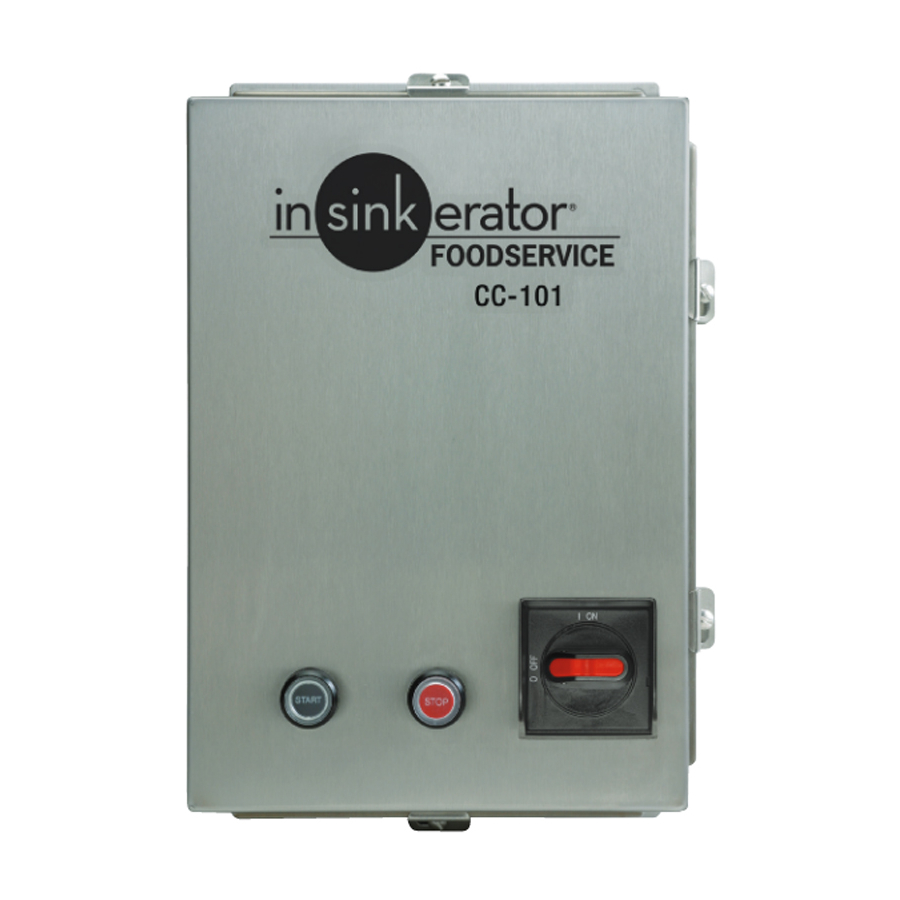
DISPOSER CONTROL CENTER
Installation Manual
Model CC-101K
WARNING indicates a hazardous situation which, if not avoided, could result in
death or serious injury.
CAUTION indicates a hazardous situation which, if not avoided, could result in
minor or moderate injury.
NOTICE is used to address practices not related to physical injury.
Please be certain that the person who installs or uses this appliance carefully reads
and understands the Safety Instructions contained in this manual.
www.insinkerator.com/foodservice
Part No. 15329 Rev. C
Advertisement
Table of Contents

Related Manuals for InSinkErator CC-101K


Summary of Contents for InSinkErator CC-101K
- Page 1 DISPOSER CONTROL CENTER Installation Manual Model CC-101K WARNING indicates a hazardous situation which, if not avoided, could result in death or serious injury. CAUTION indicates a hazardous situation which, if not avoided, could result in minor or moderate injury. NOTICE is used to address practices not related to physical injury.
-
Page 2: Table Of Contents
The warranty includes parts and labor, provided the service is performed by an InSinkErator Factory Authorized Service Center. This warranty does not apply if failure is due to: faulty or improper NOTE: This feature is set in the manual position at the electrical installation, faulty or improper plumbing installation, product abuse or misuse, or accidental damage. -
Page 3: Mounting The Control Center/Plumbing Connections
Mounting the Control Center/Plumbing Connections Electrical Connection Diagrams MOUNTING THE CONTROL CENTER Use the flanges at the back of the control center enclosure and only mount panel in the upright vertical position (door hinge is on the left). See Figure 1. If box is mounted to the sink table, recess the box so that the buttons do not extend beyond the table’s edge. -
Page 4: Electrical Connections
Replace disposer motor cover. Turn on power. LOW VOLTAGE Please read the disposer operating instructions and The CC-101K control center uses low voltage (24 V) train your personnel before operating the disposer. to operate contactor coils, solid state control circuit, The operating instructions include: push buttons, and solenoid valves. -
Page 5: Operating Instructions
Locate the water shutoff delay at the top of the printed 4. Control circuit fuse FNA2 is blown. Replace fuse. circuit board in the CC-101K (See Figure 8). Set the dip switches for the desired water shut off delay. Use the guide printed on the circuit board to set minutes of delay. - Page 6 CC-101K-5 Wiring Diagram CC-101K-6 Wiring Diagram P/N 15254 P/N 15254A ELECTRICAL SHOCK ELECTRICAL SHOCK PROPERTY DAMAGE PROPERTY DAMAGE • Turn off the electrical supply to the disposer before • Turn off the electrical supply to the disposer before • Ensure that the control center voltage and phase •...
- Page 7 CC-101K-7 Wiring Diagram CC-101K-8 Wiring Diagram P/N 15254B P/N 15254C ELECTRICAL SHOCK ELECTRICAL SHOCK PROPERTY DAMAGE PROPERTY DAMAGE • Turn off the electrical supply to the disposer before • Turn off the electrical supply to the disposer before • Ensure that the control center voltage and phase •...
Need help?
Do you have a question about the CC-101K and is the answer not in the manual?
Questions and answers