Table of Contents
Advertisement
WARNING
CAUTION
Please be certain that the person who installs or uses this appliance carefully reads and understands the Safety Instruc-
tions contained in this manual.
IN
SINK
ERATOR
Commercial
Products Group
COMMERCIAL DISPOSER
CONTROL CENTER
Installation Manual
Model CC-101K
Warnings alert you to hazards or unsafe practices which could result in severe personal injury or
death.
Cautions alert you to hazards or unsafe practices which could result in personal injury or property
damage.
Part No. 14175 - March. 1999
Advertisement
Table of Contents

Related Manuals for InSinkErator CC-101K


Summary of Contents for InSinkErator CC-101K
- Page 1 Commercial Products Group COMMERCIAL DISPOSER CONTROL CENTER Installation Manual Model CC-101K WARNING Warnings alert you to hazards or unsafe practices which could result in severe personal injury or death. CAUTION Cautions alert you to hazards or unsafe practices which could result in personal injury or property damage.
-
Page 2: Table Of Contents
TABLE OF CONTENTS INTRODUCTION............… 2 FEATURES ...............…. MOUNTING THE CONTROL CENTER ......3 PLUMBING CONNECTIONS ........PLUMBING CONNECTIONS-AQUA-SAVER ....… ELECTRICAL CONNECTIONS ........ELECTRICAL CONNECTIONS - AQUA-SAVER ..… OPERATING INSTRUCTIONS........OPERATING INSTRUCTIONS -AQUA-SAVER..... TROUBLESHOOTING............ SCHEMATIC WIRING DIAGRAMS......12-15... -
Page 3: Introduction
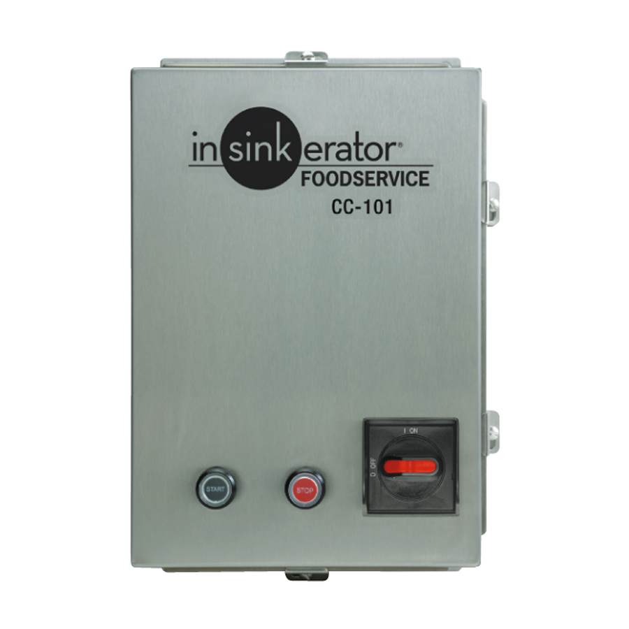
It interlocks with the front cover so that the cover cannot be opened unless the switch is in OFF position. TABLE 2. Electrical Specifications LOW VOLTAGE CONTROL Model Voltage Phase Controls operate on a 24 V solid state control circuit. CC-101K-1 120V 1/2-2 CC-101K-2 208-240V 1/2-2 ENCLOSURE CC-101K-3... -
Page 4: Mounting The Control Center
MOUNTING THE CONTROL CENTER/PLUMBING CONNECTIONS MOUNTING THE CONTROL CENTER Use flanges at the back of the control center enclosure and only mount panel in the upright vertical position (door hinge is on the left). See Figure 1. Locate control center within sight of disposer per local codes. Locate any rempote control station within sight of disposer per local codes. -
Page 5: Plumbing Connections-Aqua-Saver
PLUMBING CONNECTIONS - AQUA-SAVER PLUMBING CONNECTIONS - AQUA-SAVER FIGURE 3. Recommended installation of Aqua-Saver • The Aqua-Saver system requires the use of two (2) solenoid valves and two (2) flow control valves. • The CC101K control center is packed with a 24 V solenoid valve. An (X) GPM flow control valve is supplied with the complete disposer package. -
Page 6: Electrical Connections
ELECTRICAL CONNECTIONS ELECTRICAL CONNECTIONS CAUTION The CC-101 K control center uses low voltage (24 V) to operate contactor coils, solid state control circuit, push buttons and PROPERTY DAMAGE WARNING • Ensure that control center voltage and phase match the disposer motor and electrical supply. -
Page 7: Electrical Connections - Aqua-Saver
24 V solenoid valve is connected to the CC-101K control PROPERTY DAMAGE center, as discussed above. The solenoid valve connected to the • The 24 V solenoid valve must be connected to the CC-101K. CC101K must use the one gallon per minute flow control valve. control center. - Page 8 ELECTRICAL CONNECTIONS - AQUA-SAVER FIGURE 12. Connection diagram CC-101K-3Ø to Aqua-Saver and disposer (208-230V) FIGURE 13. Connection diagram CC-101K-3Ø to Aqua-Saver and disposer (460V)
- Page 9 ELECTRICAL CONNECTIONS - AQUA-SAVER FIGURE 14. Connection diagram CC-101K-1Ø to Aqua-Saver and disposer (120V) FIGURE 15. Connection diagram CC-101K-1Ø to Aqua-Saver and disposer (230V)
-
Page 10: Operating Instructions
OPERATING INSTRUCTIONS Please read the disposer operating instructions and train your personnel before operating the disposer. The operating instructions include: • Disposer operation. • How to feed food waste into the disposer. • How to restart the disposer after a jam condition. WARNING PERSONAL INJURY •... -
Page 11: Operating Instructions -Aqua-Saver
OPERATING INSTRUCTIONS - AQUA-SAVER OPERATING INSTRUCTIONS - AQUA-SAVER WARNING ELECTRICAL SHOCK • Line voltage is present at terminals during adjustment • Adjustment to be made by professional electrician only. CURRENT SENSING CONTROL SET-UP 1. Adjust the trip delay to mid-setting. This adjusts the length of time the water runs at full flow after grinding is completed. -
Page 12: Troubleshooting
TROUBLESHOOTING WARNING TROUBLESHOOTING • Do not put fingers or hands into the disposer. • When attempting to remove objects from a disposer, use long- handled tongs or pliers. ELECTRICAL SHOCK/PROPERTY DAMAGE • Turn power off before clearing a jam, removing an object from the disposer, or pressing the red reset button. -
Page 13: Schematic Wiring Diagrams
Schematic Wiring Diagram - Model CC-101k 120v 1Ø 1/2-2 hp WARNING CAUTION ELECTRICAL SHOCK PROPERTY DAM AGE • Turn off all electrical supply to the disposer before attempting any work on it. Use a voltmeter or circuit tester • Ensure that the control center voltage and phase match the to ensure that power is off. -
Page 14: Schematic Wiring Diagrams
Schematic Wiring Diagram - Model CC-101K 208-240v 1Ø 1/2-2 hp WARNING CAUTION ELECTRICAL SHOCK • Turn off all electrical supply to the disposer before attempting any work PROPERTY DAMAGE on it. Use a voltmeter or circuit tester to ensure that power is off. - Page 15 Schematic Wiring Diagram - Model CC-101K 208-240v 30 1/2-10 hp WARNING CAUTION ELECTRICAL SHOCK PROPERTY DAMAGE • Turn off all electrical supply to the disposer before attempting • Ensure that the control center voltage and phase match the any work on it. Use a voltmeter or circuit tester to ensure that disposer motor and electrical supply.
Need help?
Do you have a question about the CC-101K and is the answer not in the manual?
Questions and answers