Advertisement
Quick Links
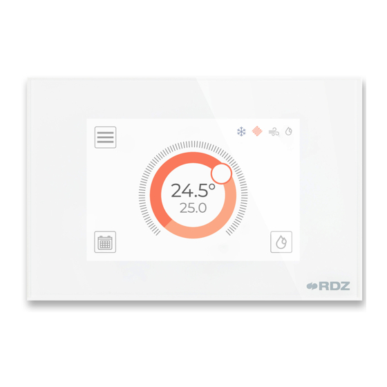
Dispositivo touch ad incasso su parete, utile alla rilevazione
e al controllo della temperatura e dell'umidità in ambiente
(Indice di Comfort). Sviluppato per la gestione dell'impianto
radiante e dell'unità di Trattamento Aria collegata.
INSTALLAZIONE A PARETE - WALL MOUNTING
• Sganciare il frontale dal guscio posteriore agendo sulla parte inferiore
del dispositivo (fig. a-b).
• Eseguire il collegamento elettrico (vedi schema sotto) senza dare
alimentazione al dispositivo; utilizzare cavi di sezione 0,5 mm
• N.B.: per il collegamento R-BUS utilizzare cavi schermati.
• Fissare con 2 viti il guscio posteriore sulla scatola di derivazione ad
incasso (fig. d-e).
• Fissare il frontale del dispositivo al guscio posteriore avendo
l'accortezza di inclinare leggermente il frontale e incastrandolo sui
2 ganci posti sulla parte superiore del guscio. Ruotare poi il frontale
verso il basso (fig. f-g).
COLLEGAMENTI E SCHEMI ELETTRICI - CONNECTIONS AND WIRING DIAGRAMS
(*)
Posizionare DIP 1-2 in posizione ON (switch sul retro dispositivo)
Set DIP 1-2 to ON position (switch on back of device)
Rif. Descrizione
+
Alimentazione dispositivo +12 VDC (+)
CH Riferimento + porta R-BUS
CL Riferimento - porta R-BUS
-
Alimentazione dispositivo -12 VDC (-)
NO Relè contatto Normalmente Aperto
C
Relè contatto Comune
NC Relè contatto Normalmente Chiuso
• COLLEGAMENTO R-BUS
• Il cavo di comunicazione tra i vari nodi è un cavo a 2 x 0,5 mm2
intrecciato e schermato, collegamento entra-esci
• La schermatura deve essere collegata creando continuità tra i vari
spezzoni di cavo e messa a terra in un solo punto della rete
• Se il dispositivo si trova all'inizio o alla fine della rete bus è necessario
impostare la terminazione (*)
CORE CRONO TH
SCHEDA INSTALLAZIONE | INSTALLATION SHEET
a
b
(fig. c).
2
+12 Vdc
0 Vdc
Alimentazione - Power Supply
Wall-mounted touch device, useful for detecting and
controlling room temperature and humidity (Comfort Index).
Designed for the management of the radiant system and
connected Air Handling Unit.
c
+
NO
CH
C
CL
NC
-
vedi schema elettrico
see wiring diagram
d
• Unhook the front panel from the rear shell by acting on the lower part
of the device (fig. a-b).
• Carry out the electrical connection (see diagram below) without supplying
power to the device; use cables with a cross-section of 0,5 mm
• N.B.: use shielded cables for the R-BUS connection.
• Fasten the rear shell to the flush-mounted junction box with 2 screws
(fig. d-e).
• Attach the front panel of the device to the rear shell, taking care to tilt
the front panel slightly by engaging it on the 2 hooks at the top of the
shell. Then rotate the front panel downwards (fig. f-g).
L
N
+
NO
CH
C
CL
NC
-
Rif. Description
+
Device power supply +12 VDC (+)
CH R-BUS port reference +
CL R-BUS port reference -
-
Device power supply -12 VDC (-)
NO Normally Open relay contact
C
Common relay contact
NC Normally Closed relay contact
• R-BUS CONNECTION
• The communication cable between the various nodes is a 2 x 0,5 mm2
twisted and shielded cable, In-Out connection
• The shield must be connected by creating continuity between the various
pieces of cable and grounded at one point in the network
• If the device is at the beginning or end of the bus network, termination
(*) must be set
1 / 4
Modello / Model
Codice / Code
CoRe CRONO TH
f
e
6600153
g
(fig. c).
2
Advertisement

Subscribe to Our Youtube Channel
Related Manuals for RDZ CORE CRONO TH


Summary of Contents for RDZ CORE CRONO TH
- Page 1 CORE CRONO TH SCHEDA INSTALLAZIONE | INSTALLATION SHEET Dispositivo touch ad incasso su parete, utile alla rilevazione Wall-mounted touch device, useful for detecting and e al controllo della temperatura e dell’umidità in ambiente controlling room temperature and humidity (Comfort Index).
- Page 2 SCHEDA INSTALLAZIONE | INSTALLATION SHEET CONFIGURAZIONI INIZIALI O AVVIO GUIDATO - STARTUP WIZARD La procedura di configurazione di CoRe CRONO TH permette di impostare The configuration procedure of CoRe CRONO TH allows the parameters i parametri necessari per un corretto funzionamento. La procedura viene required for correct operation to be set.
- Page 3 SCHEDA INSTALLAZIONE | INSTALLATION SHEET Precedente - Previous Successivo - Next +3.0 Regolazione - Setting 1. Integrazione: permette di stabilire in quale stagione impostare la 1. Integration: allows to specify in which season to set the air integration funzione di gestione dell’ Integrazione ad aria (se gestita dalle UTA). management function (if managed by AHUs).
- Page 4 SCHEDA INSTALLAZIONE | INSTALLATION SHEET Icona / Tasto - Icon / Key Descrizione Description MODALITÁ Accesso alla selezione della modalità operativa (per le Access to operating mode selection (for functionalities OPERATIVA funzionalità scaricare il Manuale Utente da QR code download User Manual from QR code at the end of OPERATING MODE riportato a fine pagina) the page)
Need help?
Do you have a question about the CORE CRONO TH and is the answer not in the manual?
Questions and answers