Advertisement
Quick Links
INSTALLATION SHEET
SCHEDA INSTALLAZIONE
INSTALLATION PRECAUTION
• Ensure that the working conditions are within the limits
stated in the TECHNICAL SPECIFICATIONS sheet.
• Do not install the device close to heat sources, equipment with
a strong magnetic field, in places subject to direct sunlight, rain,
damp, excessive dust, mechanical vibrations or shocks
• In compliance with safety regulations, the device must be
installed properly to ensure adequate protection from contact
with electrical parts. All protective parts must be fixed in such a
way as to need the aid of a tool to remove them.
IMPORTANT NOTICE FOR CORRECT DISPOSAL OF THE
PRODUCT. The symbol shown here by the side is affixed
on the device to indicate that these products cannot be
treated as urban waste and are appliances to which
the 2011/65/EU, 2012/19/EU, and 2003/108/CE European Waste
Electrical and Electronic Equipment Directive (WEEE) applies.
WALL MOUNTING
1. Unhook the back shell from the front through a screwdriver in
the proper seat
2. Lean the back shell against the wall in a position suitable to get
the connecting cable to pass through the proper opening
3. Use the slots of the back shell as template to drill 4 holes having a
diameter suitable to the bolt 5.0 mm diameter bolts are suggested
4. Insert the bolts in the holes drilled in the wall
5. Fasten the back shell at the wall with 4 screws. Countersunk
head screws are suggested
6. Make the electrical connection without powering up the device
7. Fasten the front of the device at the back shell
Front
Frontale
USER DISPLAY TH
Wall
Seat
Parete
Sede
Connection cable
Cavi di collegamento
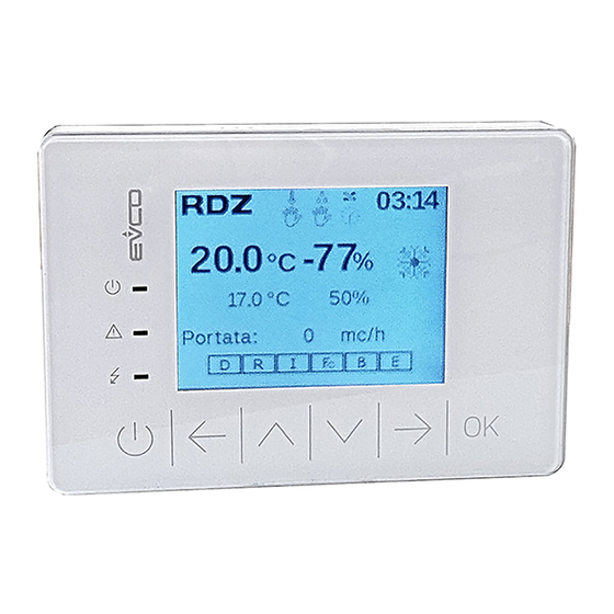
USER DISPLAY
USER DISPLAY
USER DISPLAY TH
AVVERTENZE PER L'INSTALLAZIONE
• Accertarsi che le condizioni di lavoro (temperatura
di impiego, umidità, ecc.) rientrino nei limiti indicati nei dati
riportati sulla scheda tecnica.
• Non installare lo strumento in prossimità di fonti di calore
(resistenze, condotti dell'aria calda, ecc.), di apparecchi con
forti magneti (grossi diffusori, ecc.), di luoghi soggetti alla luce
solare diretta, pioggia, umidità, polvere eccessiva, vibrazioni
meccaniche o scosse
• In conformità alle normative sulla sicurezza, la protezione
contro eventuali contatti con le parti elettriche deve
essere assicurata mediante una corretta installazione dello
strumento; tutte le parti che assicurano la protezione devono
essere fissate in modo tale da non poter essere rimosse senza
l'aiuto di un utensile.
AVVERTENZE PER IL CORRETTO SMALTIMENTO
DEL PRODOTTO. Il simbolo a lato riportato è apposto
sul dispositivo per indicare che questi prodotti non
possono essere trattati come rifiuti urbani e che
rientrano fra le apparecchiature per le quali trova applicazione
la Direttiva Europea 2011/65/UE, 2012/19/UE e 2003/108/CE,sui
rifiuti di apparecchiature elettriche ed elettroniche (RAEE).
INSTALLAZIONE A PARETE
1. Sganciare il guscio posteriore dal frontale con l'aiuto di un
cacciavite nell'apposita sede
2. Appoggiare il guscio posteriore alla parete in un punto
adeguato a far passare i cavi di collegamento attraverso
l'apposita apertura
3. Utilizzare le asole del guscio posteriore come guida per
eseguire 4 fori di un diametro adeguato al tassello.
Si consiglia di utilizzare tasselli diametro 5,0 mm
4. Inserire i tasselli nei fori eseguiti nella parete
5. Fissare il guscio posteriore alla parete con 4 viti. Si consiglia
di utilizzare viti a testa svasata piana
6. Eseguire il collegamento elettrico senza dare alimentazione
al dispositivo
7. Fissare il frontale del dispositivo al guscio posteriore
Back shell
Guscio posteriore
Opening to get the connecting cables to pass
Apertura per il passaggio dei cavi di collegamento
COD.
7041470
7041475
Slot
Asola
Advertisement

Related Manuals for RDZ User Display


Summary of Contents for RDZ User Display
- Page 1 USER DISPLAY INSTALLATION SHEET USER DISPLAY TH SCHEDA INSTALLAZIONE COD. USER DISPLAY 7041470 USER DISPLAY TH 7041475 INSTALLATION PRECAUTION AVVERTENZE PER L’INSTALLAZIONE • Ensure that the working conditions are within the limits • Accertarsi che le condizioni di lavoro (temperatura stated in the TECHNICAL SPECIFICATIONS sheet.
- Page 2 Cavi di collegamento ELECTRICAL CONNECTION COLLEGAMENTO ELETTRICO (*) Max 30 m if the control is powered externally (not powered by the USER DISPLAY Micro-switch A.T.U. controller) (*) Max 30 m se il Controllo è alimentato esternamente (non alimentato Connector 1 Connector 2 dal controllore U.T.A.)
Need help?
Do you have a question about the User Display and is the answer not in the manual?
Questions and answers