
Subscribe to Our Youtube Channel
Related Manuals for Safe Fleet DH6


Summary of Contents for Safe Fleet DH6
- Page 1 DH6/DH8 Hybrid DVR Installation Guide © Safe Fleet | All rights reserved 2022 | Part #: 700-1278 R1...
- Page 2 — This page intentionally blank — © Safe Fleet | All rights reserved 2022 | Part #: 700-1278 R1...
-
Page 3: Table Of Contents
Accessing the On-screen Display....18 Contact Safe Fleet Technical Support... . . 66 Working with Video......21 Returns.. -
Page 4: System Components
DH6/DH8 Installation Guide System Components System Components The typical installation components are listed below. • DH6/DH8 video recorder with hard drive, locking front cover, cable cover, fasteners, and mounting plate • Power harness (PH2X2MFJR) Camera Options • Analog High Definition cameras (HD3Q, HD3W, HD3U, HD3S, HD2Q, HD1W, HD1Q, or HD1S) •... -
Page 5: Required Tools & Equipment
Front cover keys for securing the removable front cover. Configuration equipment: • For on-screen configuration: portable video monitor and mouse. • For vMax Web configuration: laptop and an Ethernet cable. © Safe Fleet | All rights reserved p. 5 2022 | Part #: 700-1278 R1... -
Page 6: System Diagram
Standard Resolution and/or High Definition Cameras * Typical System Setup Purple - Signal 7 Signal Input (SIG) * The DH6 supports up to 7 channels, including 6 Video breakout harness: 2-conductor Blue - Signal 8 DH6 - VBH-6D-2SA-M standard resolution and/or high definition cameras,... -
Page 7: Installation
Technical Support at 1.844.899.7366 or PTsupport@safefleet.net for assistance. The following table outlines the physical and environmental requirements for installing a DH6/DH8 DVR: Ventilation Install the DVR away from any sort of heat outlet, heater, or AC blower. Do not operate the DVR in a closed -in area, or restrict ventilation in any way. -
Page 8: Installing The Dvr
10. When DVR installation is complete, attach the front door by hooking the door along the top edge and turning the key to the locked position. Locking front cover © Safe Fleet | All rights reserved p. 8 2022 | Part #: 700-1278 R1... -
Page 9: Installing The Video Breakout Harness
Installing the Video Breakout Harness The Video Breakout Harness (DH6: Part # VBH-6D-2SA-M – or – DH8: Part # VBH-8D-2SA-M) connects 6 (DH6) or 8 (DH8) standard resolution and/or high definition cameras, 2 Signal inputs (Signals 7 and 8) and an Alarm input (Alarm C). -
Page 10: Installing The Adapter Harness (Optional)
For additional wiring details, see the System harness (optional) Diagram on page 6. To Digital Output - Black: ground, Blue: vehicle 12V 150mA source/0V 350mA sink © Safe Fleet | All rights reserved p. 10 2022 | Part #: 700-1278 R1... -
Page 11: Firmware Updates
Completing Upgrade After restarting, the DVR may take up to 3 minutes to load and complete the upgrade. Wait until the DVR finishes loading. © Safe Fleet | All rights reserved p. 11 2022 | Part #: 700-1278 R1... -
Page 12: Post - Installation Checklist
OK. Exit the Configuration setting menu, and system setup is complete. Fasten and lock the front cover. Secure the cable cover on the DVR using the screws provided. © Safe Fleet | All rights reserved p. 12 2022 | Part #: 700-1278 R1... -
Page 13: Operation
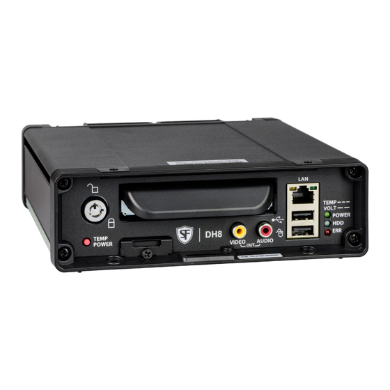
• flashes quickly when the DVR cannot power viewing with a portable monitor). up due to temperature limitations 9. Model ID (DH6 or DH8) • flashes slowly when the DVR cannot power up due to voltage limitations. 10. SD Card Slot Cover- SD card for recording low resolution ("R2") backup video stream. -
Page 14: Dvr Back Panel Features
1. GPS - SMA input connector for GPS antenna 8. EXPANSION - connector for communicating with other devices, including Student Tracking, Rear Vision 2. CAMERAS/ALARMS - video breakout harness: 6 (DH6) System, and Digital Output. or 8 (DH8) standard resolution and/or high definition cameras, 2 signal connections (signals 7 and 8) and 9. -
Page 15: Video System Status
If the system is experiencing video loss and not recording, the red light displays. On systems with primary storage consisting of dual media, both media must fail. © Safe Fleet | All rights reserved p. 15 2022 | Part #: 700-1278 R1... -
Page 16: Video Flagging
Evidence Manager. The software is supported on a Windows-based computer. For more information, see the Evidence Manager User Guide on the Safe Fleet Community. If your organization uses one of our video management applications (Commander or Depot Manager), tagged video can be automatically downloaded and made available to reviewers when your vehicle returns to the depot. -
Page 17: Health Check
WiFi RSSI Relative radio frequency signal strength: the lower the dBm value, the stronger the signal. Reported dBm of between 50-75 indicates a strong signal. © Safe Fleet | All rights reserved p. 17 2022 | Part #: 700-1278 R1... -
Page 18: Administration
User Guide here. For full-featured video review, searching, and archiving, we recommend Evidence Manager. The software is supported on a Windows-based computer. For more information, see the Evidence Manager User Guide on the Safe Fleet Community. Using the On-screen Display To use the On-screen Display: 1. - Page 19 Live camera feeds appear in a 6-up (DH6) or 8-up (DH8) grid. Tiles display according to assigned channel number (sequentially from top-left to bottom-right). DH6: if more than 6 channels are enabled the live display switches to an 8-up grid. DH8: if more than 8 channels are enabled, the live display switches to a 12-up grid.
- Page 20 Number of alarms triggered. Resets to 0 when DVR is restarted. Highlights to indicate trouble with the DVR fan. Highlights when external G-Sensor is connected. Highlights when vehicle ignition is on. © Safe Fleet | All rights reserved p. 20 2022 | Part #: 700-1278 R1...
-
Page 21: Working With Video
4. In the center of the Playback View, click the Show/Hide icon. The Playback Toolbar appears. 5. Click the icons to browse video and archive clips. Multi-camera View Playback Toolbar Metadata © Safe Fleet | All rights reserved p. 21 2022 | Part #: 700-1278 R1... - Page 22 For more information, see Metadata Details in "Title/Display Tab" on page 29. Show/Hide Playback Tool Bar Shows/hides the playback tool bar. Exit Closes the On-Screen Display © Safe Fleet | All rights reserved p. 22 2022 | Part #: 700-1278 R1...
- Page 23 The DVR retrieves a list of recorded video segments containing the specified event type. Select an item from the list, then click Play to view the video captured when the event occurred. © Safe Fleet | All rights reserved p. 23 2022 | Part #: 700-1278 R1...
-
Page 24: Basic Configuration
If GPS is installed, set GPS Time Sync ON to detect time and vehicle location Time/Display Enter the vehicle number in Main Title, and choose the information that displays as text when video appears © Safe Fleet | All rights reserved p. 24 2022 | Part #: 700-1278 R1... - Page 25 If an RGY button or Diagnostic indicator is installed, select it here. System Program Update Upload DVR configuration if necessary. Format the hard drive after all settings have been made. © Safe Fleet | All rights reserved p. 25 2022 | Part #: 700-1278 R1...
-
Page 26: Adding An Ip Camera
C12F2PD or C8Q2PD PoE Injector Kit Required A PoE (Power over Ethernet) injector kit (DH-POEKIT48-A) is required to connect a supported IP camera to DH6/DH8 recorders. For installation procedures, please see the DH6/DH8 48V PoE Injector Quick Installation Guide (part # 700-1279) on the Safe Fleet Community. -
Page 27: Adding Th4C/Dh4C Camera Feeds (Dh8-Only)
To add an RTSP-supported IP camera: Connect the camera and PoE injector. • Follow procedures in the DH6/DH8 48V PoE Injector Quick Installation Guide (part # 700-1279), available on the Safe Fleet Community. Configure the LAN2 rear panel port: •... -
Page 28: Time/Date Tab
Set the date for the DVR. GPS Time Sync If GPS is installed, set this ON to have the system time [OFF] automatically updated when satellites are detected. © Safe Fleet | All rights reserved p. 28 2022 | Part #: 700-1278 R1... -
Page 29: Title/Display Tab
If Metadata Display is ON, display the ambient temperature [F], C inside the DVR in degrees. Select F (Fahrenheit) in the USA or C (Celsius) in Canada. © Safe Fleet | All rights reserved p. 29 2022 | Part #: 700-1278 R1... - Page 30 Vehicle ignition state (highlighted=ignition on, dimmed=off) Fan failure notification (highlighted=failure, dimmed=normal) G-Sensor (GSN) G Sensor threshold incident (highlighted=threshold exceeded). For more information, see "G Sensor" on page 55 © Safe Fleet | All rights reserved p. 30 2022 | Part #: 700-1278 R1...
-
Page 31: Camera Settings
(for more information, see "Configuring Vid- eo Sources" on page 32). © Safe Fleet | All rights reserved p. 31 2022 | Part #: 700-1278 R1... - Page 32 RTSP device. Refer to the camera documentation, or contact Technical Support. 4. Set up the camera as required. © Safe Fleet | All rights reserved p. 32 2022 | Part #: 700-1278 R1...
- Page 33 The IP, port, and path data you enter in the Camera Settings RTSP screen define a connection to the camera's RTSP server (the DVR acts as the client). Check the Safe Fleet Community (see "Need Help?" on page 66) to find RTSP connection string details for supported cameras, or contact Technical Support for more information.
- Page 34 VALUE [DEFAULT] Ch (logical For IP cameras/devices and RTSP video sources: select a logical [NA], 1-12 (DH8) or 1-8 (DH6) channel) channel. The channel number determines the camera display location in live and playback views (for more information, see "Working with Video"...
-
Page 35: Configuring Signals
It is important to understand that you can also search video for signal events. For example, you can find every instance when the warning lights were activated. For more information, see the Evidence Manager User Guide on the Safe Fleet Community and "Working with Video"... - Page 36 ALM4 Note: assigning alarms to the default signals 1 through 5 is generally not recommended, since these would be continually triggered by normal vehicle operation. © Safe Fleet | All rights reserved p. 36 2022 | Part #: 700-1278 R1...
-
Page 37: Alarm Settings
Therefore, a DVR usually records in a mode that conserves storage space. If the system is wirelessly enabled with our video management software, flagged video can be automatically downloaded to your network (for more information, see the Commander User Guide or the Depot Manager User Guide on the Safe Fleet Community). - Page 38 (FPS), quality, and resolution 20, 30, 45 min settings. † These alarm settings are not available for unsupported IP cameras and RTSP streams. © Safe Fleet | All rights reserved p. 38 2022 | Part #: 700-1278 R1...
- Page 39 The signal is not active when the input is held at a high voltage level. CH 5-8/CH Click to work with alarms for the defined set of channels. CH 9-12/CH 5-8 (DH8 only) © Safe Fleet | All rights reserved p. 39 2022 | Part #: 700-1278 R1...
-
Page 40: Copying Dvr Configuration
(e.g. "SB5C" for a school bus with 5 cameras). 7. Click Store. In the confirmation that appears, click Yes. 8. Click OK. The configuration file is created on the USB device. © Safe Fleet | All rights reserved p. 40 2022 | Part #: 700-1278 R1... - Page 41 Alarms & I/O Sensor G Sensor calibration (if the external G-Sensor is installed) For more information, see ."Setting up the DVR" on page 24. © Safe Fleet | All rights reserved p. 41 2022 | Part #: 700-1278 R1...
-
Page 42: Advanced Configuration
Protected Alarm settings, click Advanced (for details, see Advanced Menu Options, below). 4. Click Back to save settings, or click Camera to configure resolution, recording speed/quality, and other camera options. © Safe Fleet | All rights reserved p. 42 2022 | Part #: 700-1278 R1... - Page 43 This reduces battery drain and required maintenance, while extending the recorder's service life. For details, see "Setting up Smart Stop" on page 45. © Safe Fleet | All rights reserved p. 43 2022 | Part #: 700-1278 R1...
- Page 44 Alarm data becomes full (see "Protected Alarm Allowance", above). In that case, new protected Alarm data overwrites existing protected data, starting with the oldest recordings. © Safe Fleet | All rights reserved p. 44 2022 | Part #: 700-1278 R1...
-
Page 45: Setting Up Smart Stop
Smart Stop powers down the DVR, DVR Recording Record-Off Delay overriding remaining Power-Off Delay time Power-Off Delay 60 Minutes 60 Minutes Maximum Maximum 4 Hours Maximum © Safe Fleet | All rights reserved p. 45 2022 | Part #: 700-1278 R1... - Page 46 In the Recording Settings menu, select suitable Record-Off Delay, Smart-Stop, and Power-Off Delay timer durations, depending on your system requirements. To ensure enough time for network communication and downloads, Safe Fleet recommends the following settings: • Record Off Delay – 10 min.
-
Page 47: Network Settings
If the IP information is changed and saved in a configuration file for upload to other DVRs, their settings must also be updated. For more information, see "Copying DVR Configuration" on page 40. Contact Safe Fleet Engineering Services or Technical Support to assign an IP address or reset the Smart-Reach Mobile wireless bridge, or for more information. - Page 48 Select Network IP Addresses Front to open the tab. Update configuration details as required (see "Menu Options" on page 50). Click Back to save settings. © Safe Fleet | All rights reserved p. 48 2022 | Part #: 700-1278 R1...
- Page 49 Select Network IP Addresses IP CAM Network to open the tab. Update configuration details as required (see "Menu Options" on page 50). Click Back to save settings. © Safe Fleet | All rights reserved p. 49 2022 | Part #: 700-1278 R1...
- Page 50 Typically, leave the HTTP Port set to 80, unless otherwise instructed by IT personnel. Note: Disable unused networks We highly recommend disabling Ethernet capability (turn Setting Type OFF) when Ethernet connectivity is not required. © Safe Fleet | All rights reserved p. 50 2022 | Part #: 700-1278 R1...
-
Page 51: Advanced Network Settings
Use the Advanced Settings (vMax Live Plus) tab to set up the DVR to connect with vMax Live Plus via a cellular modem. For more information, see the vMax Live Plus documentation available on Safe Fleet Community. Qualified IT Administrator Required A qualified IT administrator is required to perform network configuration, including assignment of IP addresses. - Page 52 Use a value between 0 and 32. Default Enter the Default Gateway IP address for communicating with the cellular [172.30.2.1] Gateway modem, as determined by a qualified network expert. © Safe Fleet | All rights reserved p. 52 2022 | Part #: 700-1278 R1...
-
Page 53: Built-In Wifi Settings
WIFI Status Note: Wireless network should not be enabled if WIFI is unused Leave Setting Type OFF when built-in WIFI is not being used. © Safe Fleet | All rights reserved p. 53 2022 | Part #: 700-1278 R1... -
Page 54: Vms Servers
A qualified IT administrator is required to perform network configuration, including assignment of IP addresses. A wireless bridge and an access point must also be installed and configured. Contact Safe Fleet Engineering Services or Technical Support for more information. To configure VMS Servers: 1. -
Page 55: G Sensor
3. If required, adjust G Sensor settings. For details, see Menu Options, below. 4. Click Back to save settings, then click Back again to return to the Configuration menu. © Safe Fleet | All rights reserved p. 55 2022 | Part #: 700-1278 R1... - Page 56 ALM1, ALMC, ALM3, ALM4 Peak Use the observed peak values to refine threshold settings. Peak values reflect detected G Sensor levels for axis, Vector, and Accident activity. © Safe Fleet | All rights reserved p. 56 2022 | Part #: 700-1278 R1...
-
Page 57: Speed Settings
Settings other than OFF trigger the selected action (S1-S10=Signal, [OFF], Log, S1 - S10, Speed Action ALM1-ALM4=Alarm, Log=DVR log entry) when the vehicle exceeds the ALM1, ALMC, ALM3, specified Speed Limit. ALM4 © Safe Fleet | All rights reserved p. 57 2022 | Part #: 700-1278 R1... -
Page 58: Gps Fencing
Rectangle - Sets the area for GPS fencing by upper left and lower right rectangular coordinates. This option only displays the "Top Left" and "Bottom Right" data entry fields. © Safe Fleet | All rights reserved p. 58 2022 | Part #: 700-1278 R1... -
Page 59: User Levels
Enter user names, passwords, and assign levels. For details, see Menu Options, below. 3. Click Back to save changes, then click Back again to return to the Configuration menu. © Safe Fleet | All rights reserved p. 59 2022 | Part #: 700-1278 R1... -
Page 60: System Settings
1. Select System to open the tab. 2. Adjust system settings as required. For details, see Menu Options, below. 3. Click Back to save changes. © Safe Fleet | All rights reserved p. 60 2022 | Part #: 700-1278 R1... - Page 61 1. Select System Scheduled Reboot 2. Set Enable to ON. 3. Set the Reboot Time (hour/minute). For details, see "Using On-screen Keyboards" on page 16. © Safe Fleet | All rights reserved p. 61 2022 | Part #: 700-1278 R1...
-
Page 62: Monitor Settings
2. Configure options as required. For details, see Menu Options, below. 3. Click Back to save settings, then click Back again to return to the Configuration menu. © Safe Fleet | All rights reserved p. 62 2022 | Part #: 700-1278 R1... - Page 63 For the Timer trigger type, select the amount of time each active video channel 30 sec. displays during rotation. For example, 10sec changes channels between valid camera inputs every 10 seconds. © Safe Fleet | All rights reserved p. 63 2022 | Part #: 700-1278 R1...
-
Page 64: Wake On Input, Digital Output
Wake on Input utilizes a connection to the DVR through the Signals port, via the Adapter Harness. • Digital Output sends a signal to an external device through the DVR Expansion port. For more information, see "System Diagram" on page 6. © Safe Fleet | All rights reserved p. 64 2022 | Part #: 700-1278 R1... - Page 65 For instructions on how to enter a value, see "Using On-screen Keyboards" on page 16. © Safe Fleet | All rights reserved p. 65 2022 | Part #: 700-1278 R1...
-
Page 66: Appendix
For product information, documentation, and support details, please visit the Safe Fleet community: https://community.safefleet.net Information in this guide is subject to change without notice. Please check the Safe Fleet community for the latest information: Contact Safe Fleet Technical Support •...
Need help?
Do you have a question about the DH6 and is the answer not in the manual?
Questions and answers