
Related Manuals for Water Analytics AquaMetrix 2300


Summary of Contents for Water Analytics AquaMetrix 2300
- Page 1 Aqua Metrix Water Analytics AquaMetrix 2300 Controller Installation & Operation Manual V1.3 ©Water Analytics 2014 All rights reserved. Last revised: February 11, 2014...
- Page 2 Statement of Limited Warranty WATER ANALYTICS warrants that this product is free from defects in workmanship and material for a period of 24 months for electronics from the date of delivery from the factory or authorized distributor under normal use.
-
Page 3: Table Of Contents
Configuring A larms, R elays, a nd N otifications ............ 2 2 5.1. Types o f M onitors ....................... 2 2 N116-133 AquaMetrix 2300 Installation and Operation Manual Page 3... - Page 4 Rebuilding a C orrupted I nternal S D C ard ............ 4 4 15. Panel M ounting D imensions ................... 4 5 N116-133 AquaMetrix 2300 Installation and Operation Manual Page 4...
-
Page 5: Overview
1. Overview 1.1. Introduction The AquaMetrix 2300 Controller is a multi-input controller that is web-enabled such that it can be setup in minutes from any web browser. It contains a number of Set-up Wizards to aid the user in entering information, much of which is not reproduced in this manual. The Wizards and most other screens in the 2300 Controller are organized by a dialogue followed by a summary page with “Submit”... -
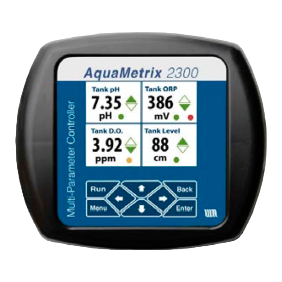
Page 6: Front Panel Display
Last Calibration date. The monitors are color coded, with green for normal operation, red for alarm condition, and yellow for an activated relay. N116-133 AquaMetrix 2300 Installation and Operation Manual Page 6... -
Page 7: Front Panel Menu
Change the network between Dynamic (DHCP) and Static IP Network Setup Network Type DHCP or Static IP; allows manual entry of static IP data Allows entry of port number Web Server Port Confirm or cancel choices Commit and Restart N116-133 AquaMetrix 2300 Installation and Operation Manual Page 7... -
Page 8: Ethernet Connection To A Network Switch Or Router
The left and right arrows on this bar are used to move the time frame by 45 minutes per click. N116-133 AquaMetrix 2300 Installation and Operation Manual Page 8... - Page 9 Figure 2 - Probe status screen. The screen lists all enabled sensors. Figure 3 - Config screen for setting up axes of graph shown in the Probe Status screen. N116-133 AquaMetrix 2300 Installation and Operation Manual Page 9...
-
Page 10: The Web Menu
Data Logging Config Set up data logging parameters Network Setup Set up web server, TFTP server, and emails System Config Miscellaneous configuration options System System doc file Documentation Advanced Miscellaneous functions Logout N116-133 AquaMetrix 2300 Installation and Operation Manual Page 10... -
Page 11: Installation And Housekeeping
Power 120-220 VAC Analog Probe inputs Ethernet Connection Fault LED System Operating LED Contact Inputs Power On LED Figure 5 - 2300 back panel. All connections are made via connectors on the back. N116-133 AquaMetrix 2300 Installation and Operation Manual Page 11... -
Page 12: Password Change
If you will be using the data logging feature of the 2300, check that the default settings for the data file are what you want. Default values are: 1. Data log files will be kept for 15 days 2. Data will be logged every 5 seconds N116-133 AquaMetrix 2300 Installation and Operation Manual Page 12... -
Page 13: Connecting And Configuring Probes
The contacts D1 and D2 are high precision optically isolated frequency counters, while D3 is not isolated. D3 uses a one-second count of the pulse rates to determine frequency. N116-133 AquaMetrix 2300 Installation and Operation Manual Page 13... -
Page 14: Probe Configuration Setup
2300’s software keeps track of the probes. Each slot may be configured as analog, digital, or virtual probes. Slot # refers to the position on the front panel and web Probe Status displays. N116-133 AquaMetrix 2300 Installation and Operation Manual Page 14... -
Page 15: The Probe Configuration Wizard
6. Probe monitors. “Monitors” are conditions that lead to actions by the 2300, such as alarms, alerts, relays, and proportional outputs. See Section 4. 7. Summary page. Prior to submitting the changes, the user may review all the information being saved, or cancel without changes. N116-133 AquaMetrix 2300 Installation and Operation Manual Page 15... - Page 16 4. Scale factor scales the input with a constant value. 5. K-Factor is a flow constant in units of pulses/volume. This inversely scales the pulses (or frequency) of an input and converts it to volume per unit time. N116-133 AquaMetrix 2300 Installation and Operation Manual Page 16...
-
Page 17: Two-Point Scaling Or Calibration
(in the case of calibration, the value of the calibration standard) into the Scaled value fields. The 2300 Controller will use these two values to scale all mAmp readings into scaled, displayed values with the units chosen on page 4 of this wizard. N116-133 AquaMetrix 2300 Installation and Operation Manual Page 17... -
Page 18: Non-Linear Scaling
Value or Edit Output Value. The Get Current Value selection loads the current raw value from the sensor and updates the selected data point. This is useful if the scaling curve N116-133 AquaMetrix 2300 Installation and Operation Manual Page 18... - Page 19 The data points can be directly changed in the Data Point List or by clicking on a plot point and moving it manually. Figure 12 - Non-linear temperature scaling example Figure 13 - Probe Configuration Wizard: Non-linear scaling. N116-133 AquaMetrix 2300 Installation and Operation Manual Page 19...
-
Page 20: Scale Factor
Three types of monitor functions are supported: High Alarm, High Control, and Periodic Counter Alarm. Email/Text notifications and relay closures are accessed the same as for the N116-133 AquaMetrix 2300 Installation and Operation Manual Page 20... -
Page 21: Configuring Differential Sensors
2300 Controller are available to the user to choose from the pull down menu on the Probe Select page. N116-133 AquaMetrix 2300 Installation and Operation Manual Page 21... -
Page 22: Configuring Alarms, Relays, And Notifications
1. Switches the panel front display from the RUN screen to a DETAILED screen for the probe that is in the alarm condition. In the detailed screen, the particular monitor line that is in alarm mode will be flashing red until acknowledged. N116-133 AquaMetrix 2300 Installation and Operation Manual Page 22... - Page 23 Figure 16. In this figure, there is a six-relay card and a four analog output card shown. Only Relays 2 and 4 are available for selection as the others are previously defined. N116-133 AquaMetrix 2300 Installation and Operation Manual Page 23...
- Page 24 The next step is to enter the control trip points. There are two inputs needed, the trip point to activate the relay and the trip point to reset, or deactivate the relay. Both are in the scaled/ N116-133 AquaMetrix 2300 Installation and Operation Manual Page 24...
- Page 25 Figure 18. Figure 17 - Probe Configuration Wizard, page 6, External ACK Control menu. Figure 18- Wiring of a switch to Contact Input 1 for acknowledgement of an alarm. N116-133 AquaMetrix 2300 Installation and Operation Manual Page 25...
-
Page 26: Configuring For Email Notification
Verizon cell phone with US number (978) 555-1111. If your provider is not on this list, search the web or ask you cell phone provider for the text email for your service. N116-133 AquaMetrix 2300 Installation and Operation Manual Page 26... -
Page 27: Logs And Data Logging
@msg.telus.com 6. Logs and Data Logging There are three types of logs that the AquaMetrix 2300 Controller generates, listed below: 1. Data Logs track scaled values for all configured Sensors and output Relays. Log entries can be saved up to once every second. Logs can also be configured to conserve space by only saving an entry if the value has changed from the previous period. -
Page 28: Data Logging Configuration Wizard
The CSV data file is named with the current date in the format of “A-131101.csv” which indicates the year, month and day for the log (November 11, 2013 for this example). Alarm logs are displayed in the Alarm Log listing on the 2300. N116-133 AquaMetrix 2300 Installation and Operation Manual Page 28... -
Page 29: User Maintenance And Passwords
7.2. Front Panel Passcodes and LCD Configuration Passcodes allow changes to the AquaMetrix 2300 from the front panel to be restricted to only those users who can authenticate the passcode. Normally, no passcodes are required. This configuration is changed from the browser setup menu. -
Page 30: Operating The 2300 Without A Network
Each point can be modified or left alone: changing any value and selecting Done (scroll down to see) will update the calibration points and reset the calibration date. N116-133 AquaMetrix 2300 Installation and Operation Manual Page 30... - Page 31 Use Done to save the entry, and Done again to save the calibration. N116-133 AquaMetrix 2300 Installation and Operation Manual Page 31...
-
Page 32: Front Panel Relay Set Points
Figure 26. Choose which point to modify, and get a numeric keypad entry screen shown on the right. If the 2300 asks for a passcode, just hit the back navigation button. The saved value is shown in parentheses. Hit Done to save the value entered. N116-133 AquaMetrix 2300 Installation and Operation Manual Page 32... -
Page 33: Front Panel Save And Restore Configuration
As with any device on local area network, one can view the 2300 outside that LAN from anywhere in the world on a so-called Wide Area Network (WAN). To do so requires the use of N116-133 AquaMetrix 2300 Installation and Operation Manual Page 33... -
Page 34: Dedicated Wireless Connection Via A Smart Phone Or Tablet
There are environments in which there is no available local area network or there is a need for a private network isolated from the network. For these settings a wireless router is the N116-133 AquaMetrix 2300 Installation and Operation Manual Page 34... -
Page 35: Static Ip Address Setup And Wired Connection
Gateway. The default static IP address of the 2300 is 192.168.7.7 so we will use these numbers in this example. On your computer use the following numbers: a. IP Address: 192.168.7.1 N116-133 AquaMetrix 2300 Installation and Operation Manual Page 35... -
Page 36: Network Setup
After entering, you must Save or Save and Restart in order for the changes to be saved. You may also specify one or more DNS server IP addresses, separated by commas (e.g. 1.2.3.4, 5.6.7.8). N116-133 AquaMetrix 2300 Installation and Operation Manual Page 36... -
Page 37: Web Server And Tftp Server Setups
If the web server port is changed, the AquaMetrix 2300 must be restarted for this change to take effect. The third submenu is the TFTP Server Setup. This configuration page allows the setting of the internal TFTP server configuration. -
Page 38: Email Keyword List
Table 4 - Email Keyword List Keyword Name Email Keyword Description System Name {{#systemname}} Name of the AquaMetrix 2300 sensor that sent the email message System Time {{#systemtime}} Time that the email message was sent Sensor Name {{#sensorname}}... -
Page 39: Email To Addresses
Email Setup page provides a mechanism to send a test email. When you select this choice, enter an existing email address from the list or enter a new one. Pressing Send Test Email will send a pre-formatted email with the subject AquaMetrix 2300 Test Message to the email addresses specified. -
Page 40: Browser C Onfiguration A Nd L Ogging O
• Send Email when GPS location changes? This is not active in the standard 2300 unit, and is only used in the 2300RT model, currently being tested. N116-133 AquaMetrix 2300 Installation and Operation Manual Page 40... -
Page 41: Unit List
12. Advanced Setup Advanced setup consists of a group of miscellaneous functions. Go to Setup/Advanced to bring up a submenu that will allow you to perform the functions listed in Table 5. N116-133 AquaMetrix 2300 Installation and Operation Manual Page 41... -
Page 42: Available I/O Card Types
The additional relays and digital inputs will appear in the drop down menus as numbers 5-8 and 4-6, respectively. In addition, they can be used as an external Acknowledge input for an Alarm. N116-133 AquaMetrix 2300 Installation and Operation Manual Page 42... -
Page 43: 7-Channel Digital Input Card
If chosen, the output may be mirrored to an analog input, or scaled to the value of any probe, real or virtual. For further information, refer to the instructions accompanying the card. N116-133 AquaMetrix 2300 Installation and Operation Manual Page 43... -
Page 44: Rebuilding A Corrupted Internal Sd Card
2300 restarts, the system is fully operational. In addition, if the system sees that the internal SD card is not accessible during startup, the user is prompted to perform the rebuild operation. N116-133 AquaMetrix 2300 Installation and Operation Manual Page 44... -
Page 45: Panel Mounting Dimensions
Panel Mounting Dimensions SIDE VIEW FRONT VIEW TOP VIEW DIMENSIONS Max Panel Thickness 0.3 in 3.65 MOUNTING HARDWARE PANEL CUTOUT PANEL MOUNTING WALL MOUNTING USING OPTIONAL ENCLOSURE N116-133 AquaMetrix 2300 Installation and Operation Manual Page 45...
Need help?
Do you have a question about the AquaMetrix 2300 and is the answer not in the manual?
Questions and answers