
Related Manuals for Water Analytics AquaMetrix AM-2252


Summary of Contents for Water Analytics AquaMetrix AM-2252
- Page 1 AM-2252 AM-2250 Multi-Parameter Multi-Parameter Dual Channel Controller Single Channel Controller Installation and Operation Manual...
-
Page 2: Table Of Contents
Contents Introduction ..............................4 Third in a Long History of Controllers ....................... 4 Specifications..............................4 AM-2252 Technical Specs ........................4 AM-2250 Technical Specs ........................6 Setup ................................7 AC Power Connection ..........................7 Conduit Connection ..........................8 Mounting ..............................8 Connecting Probes .......................... - Page 3 5.3.3 Cell Constant ............................. 26 5.3.4 Temperature ............................. 26 Flow (Exclusive to Input 1) ........................26 5.4.1 About Flow Calibration ........................27 5.4.2 Flow Calibration ..........................27 Output ................................27 Relays..............................27 6.1.1 Input (Relays 1, 2, 3, and 4 of AM-2252) .................... 28 6.1.2 Relay mode ............................
-
Page 4: Introduction
Introduction Third in a Long History of Controllers The AM-2252 multi-parameter controller is an upgraded third-generation controller built on the 30-year AquaMetrix legacy of durable and easy-to-use controllers. Many of the 2200 controllers sold those three decades ago are still in use today in some of the most hostile environments found in industry. Orders continue to come in today for 2200 pH, ORP, conductivity and flow models, years after they entered end-of-life status. - Page 5 Outputs 3 x fully scalable and optically isolated 4-20 mA. Max load: 800 Ω Analog Temperature or process output. Optional PID control for process. Channel 3 can be configure for a ratio, sum or difference of two process values. 5 independent relays: Relays 1 and 2: SPDT 5A @250 VAC Relays 3 and 4: SPST (NO) 5A @250 VAC or 5A @30 VDC (Resistive Load) Relays...
-
Page 6: Am-2250 Technical Specs
AM-2250 Technical Specs Probe Parameters Conductivity Flow 6-wire differential 6-wire differential 6-wire differential 2-electrode with Pulse output: Sensor cell constants: Paddle-wheel combination combination combination from 0.01 to 50 Magnetic Flow Temperature Pt: 100 RTD, 1000 RTD. NTC: 300Ω, 3000Ω, 10kΩ Elements Manually or automatically detected with Auto Detect Feature Sensor Input... -
Page 7: Setup
Setup AC Power Connection Caution: This instrument uses 120 or 240 50/60Hz AC power. Opening the enclosure door exposes you to potentially hazardous line power voltage which may be present on the power and relay plugs. Always remove line power before working in this area. If the relay contacts are powered from a separate source from the line power, be sure to power off before proceeding. -
Page 8: Conduit Connection
Conduit Connection The AM-2252 has six ½” (7/8” ID) conduit holes at the bottom of the enclosure. The unit is shipped with three conduit fittings and three holes plugged with liquid tight conduit seals. These must be left in unused holes to maintain the NEMA 4X integrity. -
Page 9: Connecting Probes
Connecting Probes As shown in Figure 3-4, the cover of the AM-2252 swings open to reveal a connector block for connecting probes. A label inside the controller identifies the terminals so reference to this manual is unnecessary. Figure 3-4 - This view of the inside of the front cover shows the connector for the probes. Blue indicates channel 1 and red indicates channel 2 (for AM-2252 only). -
Page 10: Analog (4-20 Ma) Outputs
The AM-2252 is a dual input controller that can work with almost all AquaMetrix sensors. Figure 3-6 shows which probes are compatible with each input. Sensor Part # Input #1 or AM-2250 Input #2 ✓ ✓ 60-Series Sensors ✓ 65-Series Sensors ✓... -
Page 11: Relays
Relays The AM-2252 contains five dry contact relays. Relays 1 and 2 are SPDT, rated 5A @ 250 VAC. Relays 3 and 4 are SPDT, normally open, and rated 5A @250 VAC or 5A @30 VDC for a resistive load. For an inductive load they are rated 2A @ 250 VAC or 2A @30 VDC. -
Page 12: Probe Setup
Probe Setup As discussed in section 3.4, the compatibility of probes differs between inputs. Both inputs support pH, ORP, ISE, and conductivity sensors. Flow sensors are exclusive to input channel #1, and sensors with 4-20 mA output are exclusive to channel #2. When powering up the 2252 the first screen presents options for configuration. -
Page 13: Ph (Inputs 1 & 2)
pH (Inputs 1 & 2) 1. Scroll down the top-level menu to select Setup and press the Enter key. 2. Select the appropriate input 3. Press Probe Selection. 4. Select and Press Enter. (As the first item in the list is the default choice.) 5. -
Page 14: Orp (Inputs 1 & 2)
8. Select the preferred units of temperature (Temp Unit): 9. Choose whether you want to keep temperature compensation. The default selection is as most application requires pH slope to be corrected for temperature. 10. Press Run to confirm that controller displays pH units and reasonable temperature values. ORP (Inputs 1 &... -
Page 15: Conductivity (Inputs 1 & 2)
5. With the exception of the two-wire combination probe, the type of temperature element must be selected. Select Temp Element to bring up the choices of temperature elements: AUTO DETECT recognizes most temperature devices. If it fails to properly configure the temperature device, check the temperature element wiring. - Page 16 correct one. For instance, if your probe has a cell constant of 1 and you choose 0.1 (perhaps in an effort to measure lower conductivity levels) your readings will be high by a factor of 10. The cell constant is typically written on a label attached to the cable.
-
Page 17: Flow (Input 1)
Concentration (%). This unit, in terms of weight per volume, is a TDS unit express as g/l. It is used for very high concentrations. It is typically used to characterize acids and bases. In order to display conductivity in terms of concentration units one must choose a conversion factor that converts mS/cm to %. The default value is 1 mS/cm = 0.5000 %. -
Page 18: Totalizer Reset
5. Set Volume Units. The choices are gallons, ft , cm , liters, and m 6. Set Time units. 7. Press to confirm that the selected flow unit is displayed correctly. Most flow sensors don’t have a temperature device, so the total flow value replaces the usual temperature value. 4.4.1 Totalizer Reset. -
Page 19: Sensors With 4-20 Ma Output (Exclusive To Input 2)
Sensors with 4-20 mA output (exclusive to Input 2) Any sensor with 4-20 mA output can be connected. Both current sourcing and current seeking options are supported. Once 4-20 mA output is selected, you must identify the units. The default units are ppm, but all units are supported. -
Page 20: Calibration
Calibration The Calibration menu automatically presents choices appropriate for the probe chosen. If the menu choices for calibration appears wrong, you probably chose the wrong probe. Note: If you select the probe type and wish to immediately calibrate you must put the controller in mode first. - Page 21 5.1.3.1 Auto Calibration In auto calibration the AM- 2252 reads the probe output when it is in a buffer and decides whether the buffer is pH 4, 7 or 10. Ideal voltages for these buffers are 177, 0 and -177 mV respectfully. If the output of the probe is within 59.16 mV (1 pH unit) from any of these values auto calibration assumes it “knows”...
-
Page 22: 3-Point Calibration
4. The screen will again display Calibrating for a few seconds and will display the results of the calibration— the efficiency and offset. An example is: If you are satisfied with the measured efficiency and offset, press Enter to accept the calibration. If not press Back to repeat... -
Page 23: Orp Calibration
which results in a temperature lag of several minutes for the element to equilibrate with the temperature of the solution. 3. The temperature calibration procedure is analogous that for manual pH calibration. It’s not necessary to immerse the probe in solution. Knowing room temperature enables you to calibrate the probe in air. As with manual pH calibration, ensure that the temperature reading settles down prior to pressing Enter. -
Page 24: Temperature
3. Observe the probe output reading and, when it has settled down, press Enter. 4. Adjust the value displayed in the next screen until it matches that of the calibration standard. Note that ORP standards can be negative so be careful to select the correct + or - sign. 5. -
Page 25: About Conductivity Calibration
5.3.1 About Conductivity Calibration As with ORP calibration there are no recognized standard calibration standards so there is no auto calibration option. Also, as with ORP, conductivity calibration standards are not buffered and can change. Stability of the conductivity standard is only a problem for standards of very low conductivity, where introduction of impurities in the solution can induce large changes in conductivity. -
Page 26: Cell Constant
4. The display will show the current conductivity reading. Adjust the conductivity reading to match the actual conductivity value of the standard. 5. Repeat for additional standards if there are any. 6. Press Enter to accept the calibration or Back to discard it. -
Page 27: About Flow Calibration
5.4.1 About Flow Calibration There is no actual calibration procedure for a flow meter. The K-factor supplied by the manufacturer sets the conversion between the meter’s pulse frequency and velocity of water flowing past the probe. The latter is proportional to the flow rate, with the proportionality constant dependent on the cross-sectional area of the pipe. The inner diameter of the pipe therefore allows the flow sensor manufacturer to convert the fluid velocity (e.g. -
Page 28: Input (Relays 1, 2, 3, And 4 Of Am-2252)
Note: All instructions assume a relay is wired as normally open (NO). If a relay is wired normally closed (NC) then activate or open should be reversed, i.e. deactivate or close. AM-2252: Relay 1, 2 Relays 3, 4 Relay 5 Am-2250: Relay 1, 2 Relay 3... - Page 29 For obvious safety reasons, the relays of every new 2252 are deactivated. The menu selection, None, signifies this choice. Selecting None is the fastest way to remove an unwanted relay setting. The following describes the process for setting a relay in one of the three possible modes in the Relay menu. 6.1.2.1 Rising Process 1.
- Page 30 6.1.2.3 Range Alarm The Range Alarm mode setting is used—as the name implies—typically as an alarm which is activated if the process value is either outside a specified range or inside it. In most applications it will be used for out-of-range process values.
-
Page 31: Fail-Safe (Relay 3,4 Of Am-2252)
6.1.3 Fail-safe (Relay 3,4 of AM-2252) Fail-safe revert NO contact such that one can use relays 3 and 4 in NC configuration so long as there is power. Please note, that input power is lost or disconnected, the relay will be held in NO position. 6.1.4 Cycle On/Off The cycle on/off parameter is very useful for preventing overshoot of a process controlling action—usually the dispensing of a chemical. -
Page 32: Relay Off Delay
4. Press Enter to confirm the displayed value or cancel by pressing Back 6.1.5 Relay Off Delay There are instances in which a process value can initially spike upon addition of a chemical. An example is acid that is dispensed very close to a pH sensor such that, when the acid is first dispensed the probe pH drops precipitously and then rises as the acid is mixed. -
Page 33: Summary
Auto: Disable override so that the relay behaves as set up. On: Activate the relay. Off: Deactivate the relay. 6.1.8 Summary The Summary menu item lists only configured relay parameters described in this section Press Back Enter to continue. 6.1.9 Relay 5 (Alarm relay) The alarm relay is quite different from other four relays. - Page 34 3. Select the channel you wish to configure 4. Select Input 5. Select Linear 6. Enter the value of the process variable that corresponds to 4 mA. 7. Enter the value of the process variable that corresponds to 20 mA. This is usually the highest value you expect to observe.
-
Page 35: Configuring Channels For Temperature
Note that the 4 mA value can be higher than the 20 mA value. This simply reverses the direction of the 4-20 mA signal as the process variable changes. 10. If for some reasons the 4-20mA output is not measured accurately on the measuring device (PLC or datalogger), one can adjust the factory 4-20 mA calibration by pressing Down Arrow (↓) button on the... -
Page 36: Pid Control
Figure 6-2 Example of pH control using relay. Proportional control ensures that the process value reaches the set-point in the most time efficient manner. Using the pH example above: The pH set-point is 9.0. As the pH rises above 9.0 the error increases and the corresponding current output increase proportionally. -
Page 37: Manual Test
• Integral. This component of the current output is proportional to the integral of the error. This is roughly equivalent to the sum of the error going back in time. • Derivative. This component of the current output is proportional to the instantaneous change in error. You can choose one to three of the three components for P, PI, PD or PID control. -
Page 38: Operation
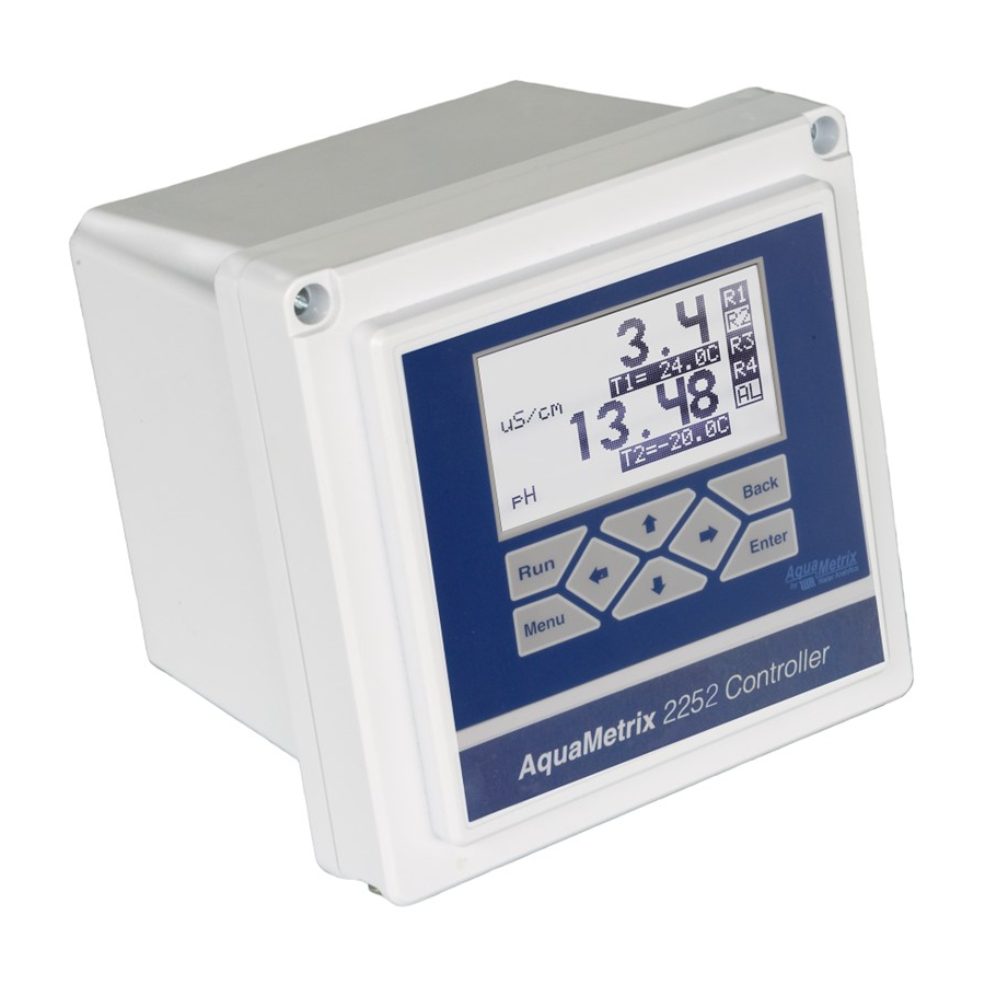
Operation Run Mode Press from just about any menu to set controller in operation mode. The screen for “Run” mode shown on Figure 7-1 below. Figure 7-1 AM-2252 in "run" mode Display Features The screen refreshes every second. A blinking dot in the top left corner indicates that measurements are occurring. The blinking dot also confirms that the controller is operating even though the process and temperature values may be so stable that they appear to be “frozen.”... -
Page 39: Diagnostics
• 4-20 output(s) freeze on the last reported value. Placing relays on hold during calibration is essential as calibration standards might activate their target (usually a pump). If, however, a relay must be kept activated during calibration/maintenance time activate Override (described in section 6.1.7) Diagnostics The Diagnostics menu has five (AM-2252) or four (AM-2250) options. -
Page 40: Factory Reset
The resistance of the temperature element should be close to the nominal resistance, which, depending on the element is usually 1100Ω (for a pt1000RTD). A resistance reading far removed from its nominal value is indicative of a defective element. • Flow. -
Page 41: Damping
Damping Signal averaging, aka “damping,” smooths fluctuating process values—both on the display and on the 4-20 mA output. The options are shown here: The signal averaging is a rolling average. For example, if damping is set to 4 seconds, then each process value data point equals the average of the preceding four points.
Need help?
Do you have a question about the AquaMetrix AM-2252 and is the answer not in the manual?
Questions and answers