Table of Contents
Advertisement
Quick Links
FT400A-A
Zone 1 Analog Wall/Desk Telephone
25500870A Rev A0 1123
Limited Warranty: This product's limited warranty can be found at
www.fedsig.com/SSG-Warranty.
SAFETY MESSAGES TO INSTALLERS AND USERS
Installation shall be carried out in accordance with the relevant, local code of
practice for Ex equipment, e.g. EN 60079-14.
The equipment is not intended for repair by the user. Repair of this equipment shall be carried out by the manufacturer
or manufacturer's authorised agent.
It is the responsibility of the end user to take suitable precautions to prevent exposure to aggressive chemicals that
may attack metals or the polymeric materials used in the construction of this equipment. Specific details of vulnerable
materials shall be provided in the instructions.
•
WARNING: ELECTRICAL HAZARD — This product should be installed by a licensed electrician according to all
electrical and building codes.
•
WARNING: HAZARDOUS AREA — Before opening the enclosure, ensure that the area is safe and that the power
conductors are not live. When replacing the faceplate, ensure that the wires or other foreign objects are not trapped
between the edges. Anything the prevents the base and the faceplate from being in direct contact nullifies the
hazardous area rating of the telephone.
•
WARNING: DISLOCATION HAZARD — To prevent injury, this apparatus must be securely attached to the floor or
wall in accordance with the installation instructions.
Failure to follow all safety precautions and instructions may result in property damage, serious injury, or death to you or
others.
NOTES:
•
FT400A-A telephones are approved for use in limited hazardous areas. Ensure that this telephone is approved for
the area in which it is to be installed.
•
FT400A-A telephones are shipped from the factory set for DTMF (tone) dialing mode. If loop disconnect (pulse)
dialing is required, program Register Number 52 appropriately.
•
Follow all appropriate electrical codes and use only approved electrical fittings for the installation.
•
If required, install primary surge protection outside of the classified area.
•
Disconnect the tip and ring conductors at the demarcation block to ensure that none of the electrical connection
circuits are live.
•
If the built-in Ring Detect Relay is to be utilized to activate an external alarm, ensure that the power conductors are
not live.
•
Using the provided 3 mm Allen
•
The telephone may be wall mounted or installed on a flat surface.
•
If the telephone is to be desktop mounted, set the base in the desired location.
:
key, remove the four faceplate screws to detach the faceplate from the base.
®
Advertisement
Table of Contents

Related Manuals for Federal Signal Corporation FT400A-A


Summary of Contents for Federal Signal Corporation FT400A-A
- Page 1 NOTES: • FT400A-A telephones are approved for use in limited hazardous areas. Ensure that this telephone is approved for the area in which it is to be installed. • FT400A-A telephones are shipped from the factory set for DTMF (tone) dialing mode. If loop disconnect (pulse) dialing is required, program Register Number 52 appropriately.
- Page 2 Table 1 Package Contents Qty Description FT400A-A Hazardous Area Desktop Telephone Parts bag containing two handset clips and screws, one 3 mm Allen key for faceplate screws, and one Ring Detect ® Relay Enable jumper wire. Table 2 Accessories and Options...
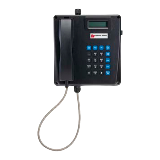
- Page 3 IEC 60079-11:2011, EN 60079-11:2012 IEC 60079-18:2014+A1:2017, EN 60079-18:2015+A1:2017 GENERAL: The FT400A-A—referred to as a “ZONE 1”—desktop telephone provides safe, reliable communications in hazardous areas that are prone to high humidity, chemical vapors, dust, and physical abuse. Hands Free operation is standard on all models, and the telephones can be programmed for speed dialing. All models have the option to install a third-party headset.
- Page 4 Figure 1 Product Standard Compliance Label Figure 2 Features Federal Signal signaling.fedsig.com...
-
Page 5: Mounting The Phone
Mounting the Phone Figure 3 Dimensions 241.0 mm Figure 4 Wall installation of base 8.72" [221.5 mm] 9.48" [240.9 mm] Federal Signal signaling.fedsig.com... -
Page 6: Desk Top Configuration
Desk Top Configuration If the telephone is to be desktop mounted, set the base in the desired location. Install the handset retainer clips on the faceplate using the supplied hardware. Wall Mount Configuration If the telephone is to be wall mounted, choose a location that is free of obstructions and permits space for wiring. Mount the base with the deepest dimension on the bottom. - Page 7 Wiring the Phone WARNING: MAINTAIN TIGHT SEAL — Use properly sized cable to ensure a gas/dust tight seal at the cable gland (M12 – 2 to 5 mm, M20 – 8 to 13 mm). Take care not to lose parts of the gland if the cap is removed. NOTE: If the cable diameter is not in the range of the M12 or M20 glands provided, an approved reducer and smaller gland can be fitted.
- Page 8 Alternate Installation Instructions for IEC60945 Maritime Compliance Figure 6 Maritime compliance IMPORTANT: Due to increased EMC/EMI and surge protection, if the phone must meet the IEC60945 Maritime Standard as well as the Zone 1 Hazardous Area requirements, it is important to follow the following instructions to ensure compliance.
- Page 9 Inserting the provided jumper wire across the Ring Detect Relay Enable terminals to enable the Ring Detect Relay. Fuses There are no replaceable fuses in the FT400A-A. The phone line fuse on the circuit board of all models is of the resettable type and is not replaceable. If the fuse trips due to an external event, it resets in a short period of time.
-
Page 10: Key Functions
Magnetic Reed Hook Switch Replacement Figure 8 Replacing the hook switch Unplug the Hook Switch Connector. Remove the screw that secures the nylon retainer. Replace the hook switch core with new one and re-secure/connect it. Key Functions While Programming Hands Free mode. Puts phone in programming mode. -
Page 11: Programming The Phone
Programming the Phone Programming Mode To enter Programming Mode, removing the handset from the cradle or by pressing the SPK key to take the phone off the hook. During the programming process, do not switch Audio modes. Press the PRG key for 1 second until a beep tone sounds and the programming prompt displays. The pass code prompt displays on the second line of the LCD. -
Page 12: Configuration Codes
1 second and the display switches back to the main register prompt. For convenience, the FT400A-A telephone has two Access Code registers; either one allows entry to programming mode. If the Access Codes are to be replaced, they should be changed one at a time. Confirm the new code by using it to get into the programming mode. -
Page 13: Programming Sheet
Programming Sheet Register Function Descriptions Entered Codes Parameters Remarks number Speed Phone number at 0 Maximum Registers 00 to 09 can dial phone 20- digit phone be accessed for dialing Phone number at 1 numbers number by pressing MR once Phone number at 2 followed by a number Phone number at 3... - Page 14 Register Function Descriptions Entered Codes Parameters Remarks number Dialing Modes One-digit code Default 1 = DTMF (RS 470) North America = 1 2 = DP 60:40 (10pps) Europe = 4 3 = DP 66:33 (10pps) 4 = DTMF (BTR 21) LCD Display Languages One-digit code Default = 1...
- Page 15 Register Function Descriptions Entered Codes Parameters Remarks number Transmit gain (1- 8) One-digit code Default = 5 using the factory setting recommended Receive gain (1 – 8) One-digit code Default = 6 using the factory setting recommended Second Access Code(4 Four-digit code Default = 5678 characters) (numeric keys, *, and #)
-
Page 16: Operating The Phone
Operating the Phone When the handset is off the cradle or the SPK key is pressed, the phone goes off hook. The LCD displays the greeting message and the current audio mode. While the phone is off hook and it detects a Call Disconnect pulse from the CO line or PABX, the phone goes on hook, even with the handset off the cradle. - Page 17 The Up and Down Keys The up and down arrow keys adjust the volume of the hearing device currently being used. Each press of these keys increases or decreases the volume by 2 dB within a range of 15 dB. The LCD displays the current volume setting for 2 seconds and then switch back to show the Audio Mode status.
-
Page 18: Push-To-Talk Handset
Press the MR key to dial out the current register phone number. The dialed number displays for 2 seconds, and then the LCD switches back to show the Audio Mode status. The arrow keys resume the volume control function. Subsequent keypad dialing resumes. NOTE: When a phone number register is clear, calling it through Quick Dial or Phone Book dialing results in no dialing at all. -
Page 19: Maintenance And Service
Product Returns: Returns require authorization from Federal Signal. Contact your Authorized Distributor for more information on our return policy or to request a return. Table 5 Replacement Parts Description Part Number FT400A-A Zone 1 Telephone Armored Handset/Cord Assembly P3026 FT400A-A Encapsulated Main PCBA P007198 FT400A-A Handset Retainer P006614 Federal Signal signaling.fedsig.com... - Page 20 2645 Federal Signal Drive, University Park, Illinois 60484 Additional translations available at signaling.fedsig.com Traducciones adicionales disponibles en signaling.fedsig.com Customer Support 1-800-344-4634+1-708-534-4756, iordersup@fedsig.com Technical Support 1-800-755-7621+1-708-587-3587, signalsupport@fedsig.com signaling.fedsig.com...
Need help?
Do you have a question about the FT400A-A and is the answer not in the manual?
Questions and answers