Table of Contents
Advertisement
Quick Links
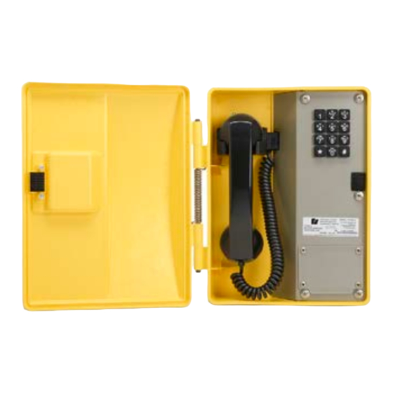
FT100C-V
Weather Resistant VoIP Telephone
25500867 Rev A0 1123
Limited Warranty: This product's limited warranty can be
found at www.fedsig.com/SSG-Warranty.
SAFETY MESSAGES TO INSTALLERS AND USERS
•
Read and understand instructions before installing or operating equipment.
•
Do not install this device near any heat sources such as radiators, heat registers, stoves, or other apparatus
(including amplifiers) that produce heat.
•
Only use attachments and accessories specified by the manufacturer.
•
Refer all servicing to qualified service personnel.
•
Prior to installation, consult local building and electrical code requirements.
•
WARNING: ELECTRICAL HAZARD — This product should be installed by a licensed electrician according to all
electrical and building codes.
•
WARNING: DISLOCATION HAZARD — To prevent injury, this apparatus must be securely attached to the floor or
wall in accordance with the installation instructions.
Electrical Performance
Ringer Output
Microphone
Receiver
Category
Ethernet I/F
Protocol
Power Input
- Method #1
- Method #2
CODECS Supported
Relay Contact
Environmental
Weather and Corrosion Resistant
Temperature
Humidity
Mechanical
Hook Switch (Cradle Switch) Life
:
Table 1 Specifications
>80 dB
Noise reducing dynamic
Hearing and compatible
10/100 MBPS
SIP RFC 3261 compatible
802.3 AF compliant PoE switch or power injector
24 Vdc at 1A power adapter
G711, A-LAW AND µ-LAW
G722.1 (SIREN7)
G722.2 (AMR-WB)
G729.1 (G729J AND G729EV)
Fuse protected to 1 A at 30 Vdc
Enclosure NEMA 3R
-22° to +140°F (-30° to +60°C)
0 to 100% RH
>1 000 000 Operations
Advertisement
Table of Contents

Related Manuals for Federal Signal Corporation FT100C-V


Summary of Contents for Federal Signal Corporation FT100C-V
- Page 1 FT100C-V Weather Resistant VoIP Telephone 25500867 Rev A0 1123 Limited Warranty: This product’s limited warranty can be found at www.fedsig.com/SSG-Warranty. SAFETY MESSAGES TO INSTALLERS AND USERS • Read and understand instructions before installing or operating equipment. • Do not install this device near any heat sources such as radiators, heat registers, stoves, or other apparatus (including amplifiers) that produce heat.
- Page 2 The FT100C-V Telephone is compatible with most SIP-based IP PBX servers that comply with SIP RFC 3261. Users can remotely monitor and program settings through a web browser to configure telephones on their network.
-
Page 3: Supported Protocols
As a SIP device, this product will operate with most IP PBX servers. Installation The Voice-over-IP (VoIP) FT100C-V Telephone is a Power-over-Ethernet (PoE 802.3af) and Voice-over-IP (VoIP) two-way communications devices that easily connect into existing local area networks (LANs) with a single cable connection. - Page 4 Figure 1 illustrates how the FT100C-V-VoIP Telephone can be installed as part of a VoIP phone system. Figure 1 Typical VoIP Installation Figure 2 Features Figure 3 Dimensions Federal Signal signaling.fedsig.com...
- Page 5 ELECTROSTATIC HAZARD: The VoIP PCBA is susceptible to damage from electrostatic discharge (ESD) and is protected by a metal shield. If it is necessary to remove the shield, take suitable precautions. SHOCK HAZARD: If using an auxiliary power supply, ensure that it is unplugged during installation to avoid an accidental shock or circuit damage.
-
Page 6: Operation
Call to and from another telephone, preferably a VoIP device, to test the unit. Operation FT100C-V-VoIP telephones may be set up for either keypad dialing or auto-dialing. If the telephone is configured for keypad, dialing operation is identical to most other single-line telephones. - Page 7 Connecting a Device to an Auxiliary Relay The FT100C-V Telephone incorporates one on-board relay located on the PCBA, which enables users to control a low current external relay or device. An external relay can control a ringer, strobe light, door lock or any other apparatus.
- Page 8 See Figure 6 and Table 3 to identify the connector locations and functions. Figure 6 Connector Locations Table 3 Connector Functions Connector Function PoE Network Connection (RJ-45) Hands free Microphone Interface/LED Interface Not used JTAG Interface Handset/Reed Switch Interface Speaker Interface Keypad Interface RS232 Port Terminal Block (see Figure 5)
- Page 9 • It is orange at 100 Mbps. Verify Network Activity The square, yellow Activity light blinks when there is network activity. Figure 7 Network Activity Reset Switch When the telephone is operational and linked to the network, use the Reset Test Function Management (RESET) switch (Figure 8) on the Telephone board to announce the telephone’s IP address, and verify that the audio is working.
-
Page 10: Announcing The Ip Address
Announcing the IP Address To announce a telephone’s current IP address, press and release the RESET switch (SW1). Do not hold the button for more than five seconds. NOTES: • The telephone will use DHCP to obtain the new IP address (DHCP-assigned address or default to 10.10.10.10 if a DHCP server is not present). -
Page 11: Maintenance And Service
If the phone is equipped with an armored cord handset, remove the anchor screw from the armored cord lanyard. Loosen the handset cable gland and pull out the cord. Install the new replacement handset and tighten the gland. Rewire the handset cord to the PCBA. Ringer Replacement To replace a ringer: Disconnect the ringer wiring from the terminal block on the PCBA. - Page 12 2645 Federal Signal Drive, University Park, Illinois 60484 Additional translations available at signaling.fedsig.com Traducciones adicionales disponibles en signaling.fedsig.com Customer Support 1-800-344-4634+1-708-534-4756, iordersup@fedsig.com Technical Support 1-800-755-7621+1-708-587-3587, signalsupport@fedsig.com signaling.fedsig.com...
Need help?
Do you have a question about the FT100C-V and is the answer not in the manual?
Questions and answers