Table of Contents
Advertisement
Quick Links
Advertisement
Table of Contents

Related Manuals for C&T Solution PC100-EHL Series


Summary of Contents for C&T Solution PC100-EHL Series
- Page 1 PC100-EHL Series PC Module PC100-EHL-1E PC100-EHL...
-
Page 2: Table Of Contents
PC100-EHL Series | User’s Manual Table of Contents Prefaces …………………………………………………….……………………………………………. 04 Revision …………………………………………………………………………………………..……………….……….. 04 Disclaimer ………………………………………………………..…….…….………………………….……………….. 04 Copyright Notice …………………………………….…………………….…………………………………………… 04 Trademarks Acknowledgment …………..………………………………………………………....04 Environmental Protection Announcement …………………………….………………….……………….. 04 Safety Precautions ………………………………………….……………………………….…………….………….. 05 Technical Support and Assistance …………………………………….…………….…………….…………….06 Conventions Used in this Manual ………………………………………………………………….….………..06 Package Contents …………………………………………………………………………………………….…………... - Page 3 PC100-EHL Series | User’s Manual Chapter 5 BIOS Setup ……………………………………………….…………….…………… 59 BIOS Introduction …….……….…………………………………..….…….…..…..…………... 60 Main Setup ……..……….………………….…………………………..….….……….………..61 Advanced Setup ………………………………………………………………………….………….. 62 5.3.1 CPU Configuration ……………………………..…………….………….….….….…..63 5.3.2 PCH-FW Configuration ……..………………………………..…..…..……….………. 64 5.3.3 SATA and RST Configuration …………………………….…………………………... 65 5.3.4 Trusted Computing ………………………………………………….…….……….…..
-
Page 4: Prefaces
Preface PC100-EHL Series | User’s Manual Prefaces Revision Revision Description Date Manual Released 2023/08/25 Disclaimer All specifications and information in this User’s Manual are believed to be accurate and up to date. C&T Solution Inc. does not guarantee that the contents herein are complete, true, accurate or non-misleading. -
Page 5: Safety Precautions
Preface PC100-EHL Series | User’s Manual Safety Precautions Before installing and using the equipment, please read the following precautions: ⚫ Put this equipment on a reliable surface during installation. Dropping it or letting it fall could cause damage. ⚫ The power outlet shall be installed near the equipment and shall be easily accessible. -
Page 6: Technical Support And Assistance
Preface PC100-EHL Series | User’s Manual Technical Support and Assistance 1. Visit the C&T Solution Inc website at https://www.candtsolution.com where you can find the latest information about the product. 2. Contact your distributor, our technical support team or sales representative for technical support if you need additional assistance. -
Page 7: Package Contents
Preface PC100-EHL Series | User’s Manual Package Contents Before installation, please ensure all the items listed in the following table are included in the package. Item Description Q’ty P100-EHL Series PC Module Screw Pack Ordering Information Model No. Product Description PC100-EHL-J6413 PC Module for Industrial Display System with Intel®... -
Page 8: Chapter 1 Product Introductions
Chapter 1 Product Introductions... -
Page 9: Overview
Chapter 1: Product Introductions 1.1 Overview The PC100-EHL series PC module is based on Intel® Celeron® Processor J6413. It supports Multi-Mode Display Module (MDM) technology which makes it more flexible in system maintaining and upgrading. It also offers modularize expansion I/O, rich connectivity interfaces, wide range (9~36VDC) DC power °... -
Page 10: Hardware Specification
PC100-EHL Series | User’s Manual Chapter 1: Product Introductions 1.2 Hardware Specification System Intel® Celeron® J6413 Processor Quad core (1.5M Cache,1.8GHz up to 3.00 GHz) Processor FC-BGA16F, Tray 10W System Chipset SoC Integrated GbE1: Intel® I210 (Support Wake-on-LAN and PXE) LAN Chipset 2.5 GbE2: Intel®... - Page 11 PC100-EHL Series | User’s Manual Chapter 1: Product Introductions Audio 1x Mic-in, 1x Line-out 2x CAN 2.0 A/B 2-pin Header (Internal) 4x RS-232/422/485 2x RS-232/422/485 (internal) 8 in / 8 out (Isolated) 2x RJ45 PC100-EHL PC100-EHL-1E Universal I/O Bracket 1x Universal I/O Bracket (By mini PCIe interface) 2x USB 3.2 Gen 2 (10 Gbps)
- Page 12 PC100-EHL Series | User’s Manual Chapter 1: Product Introductions Power Power Adapter Optional AC/DC 12V/5A, 60W Power Management Power Ignition Management (by Optional Module) Power Mode AT, ATX Power Supply Voltage 9~36 VDC Power Connector 3-Pin Terminal Blcok OVP (Over Voltage Protection)
-
Page 13: System I/O
PC100-EHL Series | User’s Manual Chapter 1: Product Introductions 1.3 System I/O 1.3.1 PC100-EHL (Top & Bottom) Removable HDD Bay SIM Card Socket Used to inserts a 2.5” HDD device Used to insert SIM card Antenna hole Used to connect an antenna for optional Mini-... - Page 14 PC100-EHL Series | User’s Manual Chapter 1: Product Introductions PC100-EHL (Left & Right) ATX power on/off switch Line-out Press to power-on or power-off the system Used to connect a speaker Power LED Mic-in Indicates the power status of the system...
-
Page 15: Pc100-Ehl-1E
PC100-EHL Series | User’s Manual Chapter 1: Product Introductions 1.3.2 PC100-EHL-1E (Top & Bottom) Removable HDD Bay SIM Card Socket Used to inserts a 2.5” HDD device Used to insert SIM card Antenna hole Used to connect an antenna for optional Mini-... - Page 16 PC100-EHL Series | User’s Manual Chapter 1: Product Introductions PC100-EHL-1E (Left & Right) ATX power on/off switch Line-out Press to power-on or power-off the system Used to connect a speaker Power LED Mic-in Indicates the power status of the system...
-
Page 17: Vesa Mounting Hole
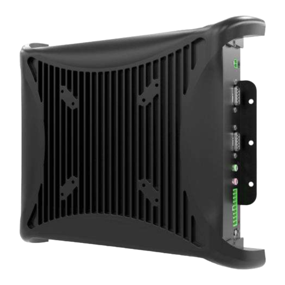
PC100-EHL Series | User’s Manual Chapter 1: Product Introductions 1.3.3 VESA Mounting Hole These are mounting holes for VESA mount (75x75mm and 100x100mm) -
Page 18: Mechanical Dimension
PC100-EHL Series | User’s Manual Chapter 1: Product Introductions 1.4 Mechanical Dimensions 1.4.1 PC100-EHL Unit: mm... -
Page 19: Pc100-Ehl-1E
PC100-EHL Series | User’s Manual Chapter 1: Product Introductions 1.4.2 PC100-EHL-1E Unit: mm... -
Page 20: Chapter 2 Switches And Connectors
Chapter 2 Switches and Connectors... -
Page 21: Switch And Connector Locations
PC100-EHL Series | User’s Manual Chapter 2: Switches and Connectors 2.1 Switch and Connector Locations 2.1.1 Top View CLR_CMOS1 AT_ATX1 COM4 COM3 COM5 LAN2 M2_KB LAN1 USB2 USB1 SIM2 SATA1 HDMI1 SIM1 DC_IN1 PCIE1 COM6 PWR_SW1 COM1 COM2 PWR_SW2 LINE_OUT1... -
Page 22: Bottom View
PC100-EHL Series | User’s Manual Chapter 2: Switches and Connectors 2.1.2 Bottom View RESET1 BAT1 SIG_OUT1 MPCIE1 M2 KE SODMM1... -
Page 23: Connector / Switch Definition
PC100-EHL Series | User’s Manual Chapter 2: Switches and Connectors 2.2 Connector / Switch Definition List of Connector / Switch Connector Location Definition AT_ATX1 AT / ATX Power Mode Switch CLR_CMOS1 Clear BIOS Switch PWR_SW1 Power Switch RESET1 Reset Switch USB2, USB1 USB Port (3.2 Gen 2 and 2.0) - Page 24 PC100-EHL Series | User’s Manual Chapter 2: Switches and Connectors LAN Port i225 LAN1 Signal LAN2_MDI0_P LAN2_MDI0_N LAN2_MDI1_P LAN2_MDI1_N R5_CT R6_CT LAN2_MDI2_P LAN2_MDI2_N LAN2_MDI3_P LAN2_MDI3_N L1_1 LAN2_SPD_2500# L2_! L2 LINK1000J L3_1 +V3.3A_LAN2 L4_1 LAN2_LINK_ACT# LAN2 LAN Port i210 Signal LAN1_MDI0_P...
- Page 25 PC100-EHL Series | User’s Manual Chapter 2: Switches and Connectors USB1 USB Port 2.0 Signal Signal USB2_VCC1 USB2_VCC1 USB2_P5_N USB2_P6_N USB2_P5_P USB2_P6_P USB2 USB Port 3.2 Gen 2 Signal Signal +V5A_USBP12 +V5A_USBP12 USB2_P1_N USB2_P2_N USB2_P1_P USB2_P2_P P1_SSRX_N P2_SSRX_N P1_SSRX_P P2_SSRX_P...
- Page 26 PC100-EHL Series | User’s Manual Chapter 2: Switches and Connectors Display Port Signal Signal DP1_TXP0 DP1_TXN3 DP1_TXN0 DP1_CFG1 DP1_TXP1 DP1_AUX+_HDMI_ DDCCLK DP1_TXN1 DP1_AUX- DP1_TXP2 _HDMI_DDCDAT DP1_HPD DP1_TXN2 DP_PWR Return DP1_TXP3 DP_PWR HDMI1 (Optional) High Definition Multimedia Interface Signal Signal HDMI_TX2+_C...
- Page 27 PC100-EHL Series | User’s Manual Chapter 2: Switches and Connectors DC_IN1 Power Input DC 9~36V Signal Power 9-36V_IN ACC Ignition GND_IN PWR_SW1 Power Button Signal PWRBT_IN# Digital I/O Signal Signal IN1_1 OUT1_1 IN2_1 OUT2_1 IN3_1 OUT3_1 IN4_1 OUT4_1 IN5_1 OUT5_1...
- Page 28 PC100-EHL Series | User’s Manual Chapter 2: Switches and Connectors LINE-OUT1 Line-out Jack Signal AGND LINEOUT_RIGHT AGND AGND LINEOUT_LEFT MIC-IN1 Mic-in Jack Signal AGND MIC_IN_R AGND AGND MIC_IN_L COM1 RS232 / RS422 / RS485 Connector Signal Signal NDCD1 NDSR1 NRXD1...
- Page 29 PC100-EHL Series | User’s Manual Chapter 2: Switches and Connectors COM2 RS232 / RS422 / RS485 Connector Signal Signal NDCD2 NDSR2 NRXD2 NRTS2 NTXD2 NCTS2 NDTR2 NRI2 COM3 RS232 / RS422 / RS485 Connector Signal Signal NDCD3 NDSR3 NRXD3 NRTS3...
- Page 30 PC100-EHL Series | User’s Manual Chapter 2: Switches and Connectors COM5 RS232 / RS422 / RS485 Connector Signal Signal CM5_DCD CM5_CTS CM5_DSR CM5_DTR CM5_RXD CM5_RI CM5_RTS CM5_TXD COM6 RS232 / RS422 / RS485 Connector Signal Signal CM6_DCD CM6_CTS CM6_DSR CM6_DTR...
- Page 31 PC100-EHL Series | User’s Manual Chapter 2: Switches and Connectors SIM1 SIM Card Socket Signal Signal P_UIM_PWR P_UIM_RST P_UIM_VPP P_UIM_CLK P_UIM_DATA SIM2 SIM Card Socket Signal Signal P1_UIM_VDD P1_UIM_RST P1_UIM_VPP P1_UIM_CLK P1_UIM_DATA P_UIM_CD ATX1 AT / ATX Power Mode Switch...
- Page 32 PC100-EHL Series | User’s Manual Chapter 2: Switches and Connectors PCIE1 Signal Signal Pull down SMB_CLK SMB_DATA 3.3V 3.3V 3.3V 3.3V PCIE_X4_RST# PCIE_X4_WAKE_N CLKOUT_PCIE_P0 CLKOUT_PCIE_N0 B14 X4SLOT_PCIE_6_TX_P B15 X4SLOT_PCIE_6_TX_N X4SLOT_PCIE_6_RX_P X4SLOT_PCIE_6_RX_N PCIEX4_PRSNT# A19- B19- SATA1 SATA with Power Connector Signal...
- Page 33 PC100-EHL Series | User’s Manual Chapter 2: Switches and Connectors M2_KB M.2 B-Key Socket Signal Signal CONFIG_3 VCC1 VCC2 FULL_CARD_POWER_O USB_D+ W_DISABLE1# USB_D- WWAN_LED# NOTCH NOTCH NOTCH NOTCH NOTCH NOTCH NOTCH NOTCH GPIO_5(O/1.8V) CONFIG_0 GPIO_6(O/1.8V) GPIO_11(0/1.8V) GPIO_7(O/1.8V) GPIO_10(O/1.8V) GPIO_8(O/1.8V) PERn1/USB3.0-Rx- USIM1_RST PERp1/USB3.0-Rx+...
- Page 34 PC100-EHL Series | User’s Manual Chapter 2: Switches and Connectors CLR_CMOS1 Clear BIOS Switch Switch Signal Clear CMOS Default Buzzer Signal Positive Negative...
- Page 35 PC100-EHL Series | User’s Manual Chapter 2: Switches and Connectors MPCIE1 Signal Signal WAKE# +3.3V Reserved Reserved +1.5V CLKREQ# UIM_PWR UIM_DATA REFCLK- UIM_CLK REFCLK+ UIM_RESET UIM_VPP Reserved Reserved Reserved PERST# PERn0 +3.3Vaux PERp0 +1.5V SMB_CLK PETn0 SMB_DATA PETp0 USB_D- Reserved...
- Page 36 PC100-EHL Series | User’s Manual Chapter 2: Switches and Connectors BAT1 Battery Signal +VBAT SIG_OUT1 VIO Display Module Connector Signal Signal PE1_TX+ PE3_RX- PE1_TX- PE4_TX+ PE1_RX+ PE4_TX- PE1_RX- PE4_RX+ PE2_TX+ PE4_RX- PE2_TX- USB_0P USB_0N PE2_RX+ Power_BTN...
- Page 37 PC100-EHL Series | User’s Manual Chapter 2: Switches and Connectors M2_KE M.2 E Key Socket Signal Signal +V3.3A USB_D+ +V3.3A USB_D- NOTCH NOTCH NOTCH NOTCH NOTCH NOTCH NOTCH NOTCH NOTCH PCIE_1_TX_DP PCIE_1_TX_DN PCIE_1_RX_DP PCIE_1_RX_DN CLKOUT_PCIE_P1 CLKOUT_PCIE_N1 M.2_E_RST# SRCCLKREQ1_N M.2_E_WAKE_L M.2_E_RST# M.2_E1_WAKE_L...
-
Page 38: Chapter 3 Front Panel Controls
Chapter 3 Front Panel Controls... -
Page 39: Users Controls
PC100-EHL Series | User’s Manual Chapter 3: Front Panel Controls 3.1 Users Controls POWER MENU INCREASE DECREASE AUTO ◼ Power Button Turns the monitor on or off. ◼ 1. Blue indicates power on. 2. Yellow indicates HDD access status. ◼ MENU / Enter Button Press to view the OSD menu. -
Page 40: Osd Operation
PC100-EHL Series | User’s Manual Chapter 3: Front Panel Controls 3.2 OSD Operation 3.2.1 Luminance ■ Brightness Adjust the luminance level of the screen. ■ Contrast Adjusts the contrast level of the screen. ■ Gamma This item allows you to on or off the Gamma function. -
Page 41: Color
PC100-EHL Series | User’s Manual Chapter 3: Front Panel Controls 3.2.3 Color ■ Color Temperature 6500K: Select the setting of screen color to be reddish white. 7500K: Select the setting of screen color to be bluish white. 9300K: Select the setting of screen color to be bluish white. -
Page 42: Chapter 4 System Setup
Chapter 4 System Setup... -
Page 43: Set Torque Force To 3.5 Kgf-Cm To Execute All The Screwing And Unscrewing
PC100-EHL Series | User’s Manual Chapter 4: System Setup 4.1 Set torque force to 3.5 kgf-cm to execute all the screwing and unscrewing In order to prevent electric shock or system damage, before removing the chassis cover, must turn off power and disconnect the unit from power source. -
Page 44: Installing Mini Pcie Card / Msata / M.2 E Key
PC100-EHL Series | User’s Manual Chapter 4: System Setup 4.3 Installing mini PCIe card / mSATA / M.2 E Key. Two mini PCIe slots with M.2 E Key Support is available on PC100 Series. M.2 E Key MiniPCIE1 / mSATA Insert mini PCIe card/mSATA module at a 45 degree angle. -
Page 45: Installing Hdd On Removable Sata Hdd Bay
PC100-EHL Series | User’s Manual Chapter 4: System Setup 4.4 Installing HDD on removable STAT HDD bay 1. To unlock the tray lock press the location highlighted at the red circle below and pull the tray towards you to remove the SATA HDD/SSD bay. -
Page 46: Installing Sim Card
PC100-EHL Series | User’s Manual Chapter 4: System Setup 4.5 Installing SIM card There are two SIM card slots are available on system chassis located next to the removable HDD bay, as shown below. Place the SIM card inside the SIM slot until you hear a click. - Page 47 PC100-EHL Series | User’s Manual Chapter 4: System Setup 3. Please refer to the table below to note which SIM slot to insert your SIM card into according to the matching Mini PCIe type. SIM Card Socket Number Matching Mini PCIe Slot SIM 1 M.2 B Key...
-
Page 48: Removing Chassis Top Cover
PC100-EHL Series | User’s Manual Chapter 4: System Setup 4.6 Removing chassis top cover 1. To remove the chassis top cover, there are 6 screws to be unscrewed at the locations highlighted by the red circles below. 2. Once all six screws are removed, the chassis top cover can be lifted up as shown below. -
Page 49: Installing Antenna
PC100-EHL Series | User’s Manual Chapter 4: System Setup 4.7 Installing antenna 1. Remove 3 screws located at the back of the system as pictured below. The screw locations are highlighted in red. 2. Remove 4 screws located at the front and side face of the system as pictured below. The screw locations are highlighted in red. - Page 50 PC100-EHL Series | User’s Manual Chapter 4: System Setup 4. Pass the RF connector at the end of the cable around the gap between the iron piece and the motherboard and connect it to the communication module。 5. Put on washer and fasten the nut with antenna jack as indicated below.
- Page 51 PC100-EHL Series | User’s Manual Chapter 4: System Setup 7. Fasten the 4 screws located at the front and side face of the system as pictured below. The screw locations are highlighted in red. 8. Assemble the antenna and antenna jack together.
-
Page 52: Assembling Chassis Top Cover
PC100-EHL Series | User’s Manual Chapter 4: System Setup 4.8 Assembling chassis top cover 1. Ensure thermal pad is in place on the CPU thermal block. 2. Close the chassis top cover following the below direction and make sure the aluminum part on the... - Page 53 PC100-EHL Series | User’s Manual Chapter 4: System Setup 3. Fasten the 6 screws to lock the system body with top cover. The locations are highlighted by the red circles below.
-
Page 54: Connecting Pc Module With Vio Display Module
PC100-EHL Series | User’s Manual Chapter 4: System Setup 4.9 Connecting PC module with VIO display module 1. Place the PC module with its connector facing the back of VIO display module as shown in the picture below. 2. Ensure the PC Module is aligned with the VIO Display Module and push it down gently. -
Page 55: Pc100-Ehl-1E Installing Pcie Expansion Card
PC100-EHL Series | User’s Manual Chapter 4: System Setup 4.10 PC100-EHL-1E Installing PCIe expansion card 1. Unscrew the 6 screws indicated at the circles in the photos below. 2. Once unscrewed, remove the top cover of PC module as shown below. - Page 56 PC100-EHL Series | User’s Manual Chapter 4: System Setup 3. Unscrew the 3 screws below indicated at the locations highlighted below. 4. Then, unscrew the screw indicated in the red circle below. 5. Attach the PCIe expansion card and then fasten the screw in the circle indicated below.
- Page 57 PC100-EHL Series | User’s Manual Chapter 4: System Setup 6. Install the PCIe/PCI card according to direction indicated in the picture below. 7. Ensure the gold fingers are inserted properly into the slot. 8. Fasten the 3 screws indicated at the locations in the red circles below.
- Page 58 PC100-EHL Series | User’s Manual Chapter 4: System Setup 9. Replace the chassis top cover and make sure the aluminum part on the top cover is touching the thermal pad on CPU thermal block. 10. Fasten the 6 screws indicated by the red circles in the pictures below.
-
Page 59: Chapter 5 Bios Setup
Chapter 5 BIOS Setup... -
Page 60: Bios Introduction
PC100-EHL Series | User’s Manual Chapter 5: BIOS Setup 5.1 BIOS Introduction The BIOS provides an interface to modify the configuration. When the battery is removed, all the parameters will be reset. BIOS Setup Power on the embedded system and by pressing <Del> immediately allows you to enter the setup screens. -
Page 61: Main Setup
PC100-EHL Series | User’s Manual Chapter 5: BIOS Setup 5.2 Main Setup Press <Del> to enter BIOS CMOS Setup Utility. The Main setup screen is showed as following when the setup utility is entered. System Date/Time is set up in the Main Menu. -
Page 62: Advanced Setup
PC100-EHL Series | User’s Manual Chapter 5: BIOS Setup 5.3 Advanced Setup... -
Page 63: Cpu Configuration
PC100-EHL Series | User’s Manual Chapter 5: BIOS Setup 5.3.1 CPU Configuration Item Options Description Intel (VMX) Virtualization Disabled, When enabled, a VMM can utilize the Technology Enabled[Default] additional hardware capabilities provided by Virtualization Technology. Active Processor Cores All[Default] Number of cores to enable in each processor package. -
Page 64: Pch-Fw Configuration
PC100-EHL Series | User’s Manual Chapter 5: BIOS Setup 5.3.2 PCH-FW Configuration... -
Page 65: Sata And Rst Configuration
PC100-EHL Series | User’s Manual Chapter 5: BIOS Setup 5.3.3 SATA and RST Configuration Item Options Description Port0 ~1 Disabled, Enable or Disable SATA Port. Enabled[Default] Hot Plug Disabled, Designates this port as Hot Pluggable. Enabled[Default] SATA Device Type Hard Disk Drive[Default] ,... -
Page 66: Trusted Computing
PC100-EHL Series | User’s Manual Chapter 5: BIOS Setup 5.3.4 Trusted Computing Item Options Description Security Device Support Enabled[Default] , Enable/Disable BIOS support for security Disabled, device. O.S. will not show Security Device.TCG EFI protocol and INT1A interface will not be available. -
Page 67: Acpi Setttings
PC100-EHL Series | User’s Manual Chapter 5: BIOS Setup 5.3.5 ACPI Settings Item Options Description Enable Hibernation Disabled , Enables or Disables System ability to Enabled[Default], Hibernate (OS/S4 Sleep State). This option may not be effective with some operating systems. -
Page 68: Super Io Configuration
PC100-EHL Series | User’s Manual Chapter 5: BIOS Setup 5.3.6 Super IO Configuration This setting allows you to select options for the Super IO Configuration, and change the value of the selected option. Item Description Serial Port 1 Configuration Set Parameters of Serial Port 1 (COMA). - Page 69 PC100-EHL Series | User’s Manual Chapter 5: BIOS Setup ◼ Serial Port 1 Configuration Item Options Description Serial Port Disabled, Enable or Disable Serial Port (COM). Enabled[Default] Change Settings Auto[Default], This item allows you to change the address & IO=3F8h; IRQ=4; , IRQ settings of the specified serial port.
- Page 70 PC100-EHL Series | User’s Manual Chapter 5: BIOS Setup ◼ Serial Port 2 Configuration Item Options Description Serial Port Disabled, Enable or Disable Serial Port (COM). Enabled[Default] Change Settings Auto[Default], This item allows you to change the address & IO=2F8h; IRQ=3; , IRQ settings of the specified serial port.
- Page 71 PC100-EHL Series | User’s Manual Chapter 5: BIOS Setup ◼ Serial Port 3 Configuration Item Options Description Serial Port Disabled, Enable or Disable Serial Port (COM). Enabled[Default] Change Settings Auto[Default], This item allows you to change the address & IO=3E8h; IRQ=7; , IRQ settings of the specified serial port.
- Page 72 PC100-EHL Series | User’s Manual Chapter 5: BIOS Setup ◼ Serial Port 4 Configuration Item Options Description Serial Port Disabled, Enable or Disable Serial Port (COM). Enabled[Default] Change Settings Auto[Default], This item allows you to change the address & IO=2E8h; IRQ=7; , IRQ settings of the specified serial port.
- Page 73 PC100-EHL Series | User’s Manual Chapter 5: BIOS Setup ◼ Serial Port 5 Configuration Item Options Description Serial Port Disabled, Enable or Disable Serial Port (COM). Enabled[Default] Change Settings Auto[Default], This item allows you to change the address & IO=2F0h; IRQ=7; , IRQ settings of the specified serial port.
- Page 74 PC100-EHL Series | User’s Manual Chapter 5: BIOS Setup ◼ Serial Port 6 Configuration Item Options Description Serial Port Disabled, Enable or Disable Serial Port (COM). Enabled[Default] Change Settings Auto[Default], This item allows you to change the address & IO=2E0h; IRQ=7; , IRQ settings of the specified serial port.
-
Page 75: Hardware Monitor
PC100-EHL Series | User’s Manual Chapter 5: BIOS Setup 5.3.7 Hardware Monitor These items display the current status of all monitored hardware devices/ components such as voltages and temperatures. Item Options Description Smart Fan Function Disabled[Default], Enabled or Disable Smart Fan... - Page 76 PC100-EHL Series | User’s Manual Chapter 5: BIOS Setup ◼ Smart Fan Mode Configuration Item Options Description Fan1 SmartFan Control Manual Duty Mode, Smart Fan Mode Select Auto Duty-Cycle Mode[Default], Temperature 1~4 1~100 Auto fan speed control. SMART FAN IV...
-
Page 77: Power Ign Mode
PC100-EHL Series | User’s Manual Chapter 5: BIOS Setup 5.3.8 Power IGN Mode Item Options Description IGN Setting Bypass mode[Default] Bypass: BIOS will not control IGN Module, Write IGN Write IGN: BIOS will write setting to IGN module Power On Delay... -
Page 78: Wake System From S5
PC100-EHL Series | User’s Manual Chapter 5: BIOS Setup 5.3.9 Wake system from S5 Item Options Description Wake system from S5 Disabled[Default] , Enable or disable System wake on alarm event. Fixed Time, Select FixedTime, system will wake on the Dynamic Time, hr::min::sec specified. -
Page 79: Serial Port Console Redirection
PC100-EHL Series | User’s Manual Chapter 5: BIOS Setup 5.3.10 Serial Port Console Redirection Item Options Description Console Redirection Disabled[Default], These items allows you to enable or disable Enabled COM1 console redirection... -
Page 80: Usb Configuration
PC100-EHL Series | User’s Manual Chapter 5: BIOS Setup 5.3.11 USB Configuration Item Options Description Legacy USB Support Enabled[Default] Enables Legacy USB support. AUTO option Disabled disables legacy support if no USB devices are Auto connected. DISABLE option will keep USB devices available only for EFI applications. -
Page 81: Network Stack Configuration
PC100-EHL Series | User’s Manual Chapter 5: BIOS Setup 5.3.12 Network Stack Configuration Item Options Description Network Stack Disabled[Default] , Enable/Disable UEFI Network Stack. Enabled IPv4 PXE Support Disabled[Default] , Enable/Disable IPv4 PXE boot support. If Enabled disabled, IPv4 PXE boot support will not be available. -
Page 82: Chipset
PC100-EHL Series | User’s Manual Chapter 5: BIOS Setup 5.4 Chipset This section allows you to configure and improve your system and allows you to set up some system features according to your preference. -
Page 83: System Agent (Sa) Configuration
PC100-EHL Series | User’s Manual Chapter 5: BIOS Setup 5.4.1 System Agent (SA) Configuration Item Options Description VT-d Disabled, VT-d capability. Enabled [Default] Above 4GB MMIO BIOS Enabled[Default] , Enable/Disable above 4GB assignment Disabled MemoryMappedIO BIOS assignment\n\nThis is enabled automatically when Aperture Size... - Page 84 PC100-EHL Series | User’s Manual Chapter 5: BIOS Setup ◼ Memory Configuration Item Options Description Max TOLUD Dynamic[Default], Maximum Value of TOLUD. Dynamic 1GB, assignment would adjust TOLUD 1.25GB, automatically based on largest MMIO length 1.5 GB, of installed graphic controller 1.75 GB,...
- Page 85 PC100-EHL Series | User’s Manual Chapter 5: BIOS Setup ◼ Graphic Configuration Item Options Description GTT Size 2MB, Select the GTT Size . 4MB, 8MB[Default] Aperture Size 128MB, Select the Aperture Size. 256MB[Default] , Note : Above 4GB MMIO BIOS assignment is...
-
Page 86: Pch-Io Configuration
PC100-EHL Series | User’s Manual Chapter 5: BIOS Setup 5.4.2 PCH-IO Configuration Item Options Description Restore AC Power Loss Power On, Specify what state to go to when power is re- Power Off [Default] , applied after a power failure (G3 state). - Page 87 PC100-EHL Series | User’s Manual Chapter 5: BIOS Setup ◼ PCI Express Configuration...
- Page 88 PC100-EHL Series | User’s Manual Chapter 5: BIOS Setup ◼ PCI Express Root Port 3 /4 /5 /7 Item Options Description PCI Express Root Port Disabled, Control the PCI Express Root Port. Enabled [Default] 3 /4 /5 /7 ASPM Disabled [Default] ,...
- Page 89 PC100-EHL Series | User’s Manual Chapter 5: BIOS Setup ◼ HD Audio Configuration Item Options Description HD Audio Disabled, Control Detection of the HD-Audio device. Enabled [Default] Disabled = HDA will be unconditionally disabled Enabled = HDA will be unconditionally enabled.
-
Page 90: Security
PC100-EHL Series | User’s Manual Chapter 5: BIOS Setup 5.5 Security Security menu allow users to change administrator password and user password settings. ◼ Administrator Password This item allows you to set Administrator Password. ◼ User Password This item allows you to set User Password. - Page 91 PC100-EHL Series | User’s Manual Chapter 5: BIOS Setup ◼ Security Boot Item Options Description Secure Boot Disabled [Default] , Secure Boot feature is Active if Secure Boot is Enabled Enabled,Platform Key(PK) is enrolled and the System is in User mode.
- Page 92 PC100-EHL Series | User’s Manual Chapter 5: BIOS Setup ◼ Key Management Item Options Description Factory Key Provision Disabled [Default] , Install factory default Secure Boot keys after Enabled the platform reset and while the System is in Setup mode...
-
Page 93: Boot
PC100-EHL Series | User’s Manual Chapter 5: BIOS Setup 5.6 Boot This menu allows you to setup the system boot options. Item Options Description Setup Prompt Timeout 1[Default] Number of seconds to wait for setup activation key. 65535(0xFFFF) means indefinite waiting. -
Page 94: Save & Exit
PC100-EHL Series | User’s Manual Chapter 5: BIOS Setup 5.7 Save & Exit This setting allows users to configure the boot settings. ■ Save Changes and Reset This item allows user to reset the system after saving the changes. This item allows user to reset the system after saving the changes. -
Page 95: Appendix Wdt & Gpio
Appendix WDT & GPIO This appendix provides the sample codes of WDT (Watch Dog Timer) and GPIO (General Purpose Input/ Output). -
Page 96: Wdt Sample Code
PC100-EHL Series | User’s Manual Appendix – WDT & GPIO WDT Sample Code WDT Setting Psuedo Code // IO Address 0xA16 is time value // IO Address 0xA15 is WDT enable and configuration Example, Set 0xA16=-0x03, 0xA15=0x31, it will reset after 3 seconds... -
Page 97: Gpio Sample Code
PC100-EHL Series | User’s Manual Appendix – WDT & GPIO GPIO Sample Code GPIO Setting IO_DI8 I/O 0xA03h Bit7 IO_DO8 I/O 0xA02h Bit7 IO_DI7 I/O 0xA03h Bit6 IO_DO7 I/O 0xA02h Bit6 IO_DI6 I/O 0xA03h Bit5 IO_DO6 I/O 0xA02h Bit5 IO_DI5... - Page 98 Copyright © C&T Solution Inc. All Rights Reserved www.candtsolution.com...
Need help?
Do you have a question about the PC100-EHL Series and is the answer not in the manual?
Questions and answers