Table of Contents
Advertisement
Quick Links
Advertisement
Table of Contents

Related Manuals for JOHNSON SYSTEMS PWS-70P-DMX

Summary of Contents for JOHNSON SYSTEMS PWS-70P-DMX
- Page 1 Wall Station (PWS) Installation Guide and User Manual JOHNSON SYSTEMS INC. WWW.JOHNSONSYSTEMS.COM 1923 Highfield Crescent S.E. Calgary, Alberta, Canada T2G 5M1 tel: 403.287.8003 fax: 403.287.9003 e-mail: info@johnsonsystems.com website: www.johnsonsystems.com...
-
Page 2: Table Of Contents
Contents Characteristics ....................4 Drawings & Details ..................4 Description of Operation ..................6 Installation .......................6 Model PWS-70P-DMX ..................7 Model PWS-20P-RETRO ................10 Installation Procedure ..................13 PWS Removal ....................13 Replacement Plastic Kits ................14 Presidor™ Adaptor Plates ................14 Presidor™ Surface Boxes ................14 Initial Set Up and Station Configuration............15 Power Up ....................15... - Page 3 Introduction DMX Snapshot and Multi-Zone Controls Presidor™ Wall Stations (PWS) represent the next step in Architainment Lighting Controls. Intuitive operation is coupled with state-of-the-art capacitive touch technology permitting powerful distributed lighting controls for single or multi-room environments. Attractive 1 gang “Patent Pending” design is supported by color-matched adapter plates up to 7 gang and surface mount back boxes.
-
Page 4: Characteristics
Characteristics • Voltage: Model #PWS-70P-DMX; 5 - 48VDC operational range. 48VDC when used with PRLC-4 Room Linker/Combiner (48VDC supplied by PRLC-4). Model #PWS-20P-RETRO; 24 - 48VDC operational range. Must exceed 12VDC at last station. • Power Consumption: < 1 Watt per station during operation and < 1⁄4 Watt during standby mode. - Page 5 Drawings & Details Model: Room Linker/Combiner (PRLC-4) Model: PRLCR-4U PRLC 19" Wall Rack, 4 rack units. Supports up to 4 x PRLC-4 Hinged Front Rear Wall Tub WWW.JOHNSONSYSTEMS.COM...
-
Page 6: Description Of Operation
Installation There are two models of PWS, both are available in white or black. For use in applications where 2 shielded twisted pair wiring capable of Model# PWS-70P-DMX DMX512 protocol exists. For use in legacy installations using analog wiring. Model# PWS-20P-RETRO Although both models share the same operation, the station hardware, installation and wiring of each is slightly different due to the different data protocol used. -
Page 7: Model Pws-70P-Dmx
Model PWS-70P-DMX Model #PWS-70P-DMX is designed for new applications where CAT5/5e or CAT6 can be provided or retrofit applications where existing shielded 2 or 3 twisted pair wiring capable of RS485/DMX512 exists (eg. Belden #9773). Capable of up to 70 presets, this model will accept DMX512 on its input and output DMX512 when configured as a room Main Station. - Page 8 Typical PWS-70P-DMX Wiring and Connection Detail Using Belden #9773 Typical PWS-70P-DMX Single Room Wiring Topology #1 DIP SWITCH #2 ON FOR 1st & LAST ROOM STATIONS Typical PWS-70P-DMX Single Room Wiring Topology #2 DIP SWITCH #2 ON FOR 1st & LAST ROOM STATIONS WWW.JOHNSONSYSTEMS.COM...
- Page 9 Typical PWS-70P-DMX Multi-room Wiring Topology PWS-70P-DMX Cat 5/5e/6 Interconnect PRLC - Room Linker Combiner DMX IN from Console or DMX Source MAIN SECONDARY 1 SECONDARY 2 AUX Sensor / Contact Cat 5/5e/6 Patch Cable To Secondary PWS 3-14 Cat 5/5e/6...
-
Page 10: Model Pws-20P-Retro
Model PWS-20P-RETRO Model PWS-20P-RETRO is designed specifically for use in Heritage Buildings using existing wiring (typically analog) not capable of RS485. Communication is performed via a proprietary Unipolar Bi-Directional (UBD) low baud rate protocol. This permits digital control upgrades to facilities that would otherwise be faced with a very expensive wiring replacement cost! Multiple stations must be series or daisy-chained. - Page 11 Typical PWS-20P-RETRO Wiring and Connection Detail Typical PWS-20P-RETRO Single Room Wiring Topology #1 Typical PWS-20P-RETRO Single Room Wiring Topology #2 WWW.JOHNSONSYSTEMS.COM...
- Page 12 Typical PWS-20P-RETRO Multi-Room Wiring Topology PWS-20P-RETRO Multi Room Interconnect PRLC - Room Linker Combiner (Optional) Cat 5/5e/6 Patch Cable DMX IN from Console or DMX Source MAIN SECONDARY 1 SECONDARY 2 AUX Sensor / Contact To Secondary PWS 3-14 WWW.JOHNSONSYSTEMS.COM...
-
Page 13: Installation Procedure
6. Set the dip switches as required for Main/Secondary PWS, end-of-line termination. See chart on page 7 for model# PWS-70P-DMX and page 10 for model# PWS-20P-RETRO. 7. Hook the PWS sub-assembly on to the top of the wall plate with the face panel light pipes facing upward. -
Page 14: Replacement Plastic Kits
Replacement Plastic Kits PWS-MOUNT-W Replacement PWS Mounting Kit. 4 Piece Set, White. PWS-MOUNT-B Replacement PWS Mounting Kit. 4 Piece Set, Black. Presidor™ Adaptor Plates For installation where oversize back boxes exist, Presidor™ Adaptor Plates are engineered for exact fit with Presidor™... -
Page 15: Initial Set Up And Station Configuration
Initial Set Up and Station Configuration • POWER UP • Upon power up, the PWS will briefly display the Presidor™ logo and will then default to the preset page that was last active before power down. In the case of a new station it is shipped from the factory defaulted with the first 10 presets only and displayed on two pages of five presets each in the color of teal. -
Page 16: Initial Setup And Configuration
Status LED's • INITIAL SETUP AND CONFIGURATION • Pressing the SETTINGS icon (4 above) right of the screen will access the SETTINGS menu where configuration and customization of each PWS can be performed. Each icon will access a screen menu page permitting customization of each PWS. - Page 17 1. PASSWORD / SECURITY LOCK Each PWS requires a valid Password entry to access certain functions. Access via the Security Lock icon, the lock symbol will display red when locked and no lock symbol when unlocked. Each PWS will default to a “locked” state with access to only select functions for protection of programing and restriction of use.
- Page 18 NEW USER PASSWORD A new USER PASSWORD may be entered in two ways: a) Enter the old PASSWORD, press [OK]. If you return to the PASSWORD screen before a sleep timeout, the [n] key will now be active. Pressing the [n] key will show “NewUP”. A New USER PASSWORD entry will always be displayed in red to distinguish it from the normal password entry mode.
- Page 19 NEW ADMIN PASSWORD A System Administrator can reset both the ADMIN and USER PASSWORD's and access all programming features of the PWS. Pressing the [n] key will toggle between the following two screens, or an ADMIN USER can reset both. This allows either the ADMIN or USER password to be reset depending on which is selected.
- Page 20 2. DMX SETUP Main PWS DMX set up. ADMIN security access only. This menu is used to set up the DMX mask for each room, configure the operation of room specific (unmasked) channels, and set the external DMX source input priority in conjunction with the PWS Main station DMX output.
- Page 21 EXTERNAL DMX SOURCE CONFIGURATION ADMIN PASSWORD required to access. Pressing the wrench icon in the screen below will access a page for DMX input priority set up of the Main PWS. One of the following three modes of operation can be selected: DMX IN PRIORITY - Locks out PWS DMX Output and passes external DMX Input (Control Console) to the PWS DMX Output in real time.
- Page 22 3. PRESET ENABLE/DISABLE Permits selection of the number of presets required. A Main PWS is capable of up to 70 presets (Model# PWS-70P-DMX) or 20 presets (Model# PWS-20P-RETRO). Both versions are shipped from the factory with only the first 10 presets enabled. To enable more or less presets and select color choices: a) Enter your ADMIN PASSWORD.
- Page 23 6. AUX SWITCH INPUT - Assigns external contact to the Main PWS Auxiliary Input. Contact can be assigned as maintained, momentary, normally open or normally closed to activate one or two presets. Very popular gallery automation feature for museums and art galleries. The preset numbers can be changed. 7.
- Page 24 Press the back arrow to return to EDIT SCHEDULE. DAY OF WEEK - Set the day(s) of week. Press the back arrow to return to EDIT SCHEDULE. PRESET NUMBER - Select the PRESET you wish to activate at the previously selected time and days.
- Page 25 9. PROXIMITY - Motion detection. Sensitivity selection of the proximity sensor for auto recognition. PWS will automatically “wake up” from its Low Power/Energy Saving “SLEEP MODE” when it detects a user within range of it. Maximum Infrared detection distance approx. 6’ or 1.5m. 10.
-
Page 26: Recording A Preset
RECORDING A PRESET Press and hold a preset will take you to the following. There are two ways to record a PRESET: 1. DMX SNAPSHOT - This method of PRESET recoding requires an external source of DMX512 (control console or similar) and is commonly used in theatrical and large architectural applications. -
Page 27: Program A Preset
LABEL EDITOR - Pushing the LABEL button in this menu allow for a customized labeling of the PRESET through the alphanumeric keypad. Enter the desired preset name and press the OK button. This can be done for each PRESET as required. DIM - This button allows you to quickly select the entire PRESET to operate as a Dimmer or a Non-Dim. - Page 28 Only an ADMIN can record. • With a valid ADMIN PASSWORD entered, access to all buttons and features are available to record your custom PRESET. All buttons remain the same as previously detailed in recording a “DMX Snapshot” above with the exception of the LEVELS button. Pushing this button opens access to all the DMX channels that were previously set for this Main PWS in the DMX SETUP.
-
Page 29: Preset Playback
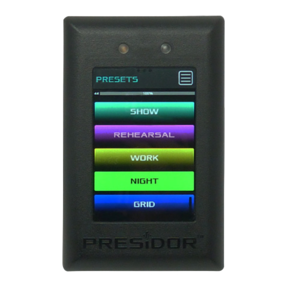
PRESET PLAYBACK Navigate to the desired preset and tap the preset. Positive preset activation will be indicated visually by the preset becoming a solid color and audibly if the audio feature has been selected and set. The gray bar at the top of the display will fade across matching the FADE TIME programmed and the PRESET output level will display the real-time DMX fading from 0-100%. - Page 30 User Manual Rev. 3 • November 2021 WWW.JOHNSONSYSTEMS.COM 1923 Highfield Crescent S.E. Calgary, Alberta, Canada T2G 5M1 tel: 403.287.8003 fax: 403.287.9003 e-mail: info@johnsonsystems.com website: www.johnsonsystems.com...