Table of Contents
Advertisement
Quick Links
Advertisement
Table of Contents

Related Manuals for AMPTO ITWIN 55


Summary of Contents for AMPTO ITWIN 55
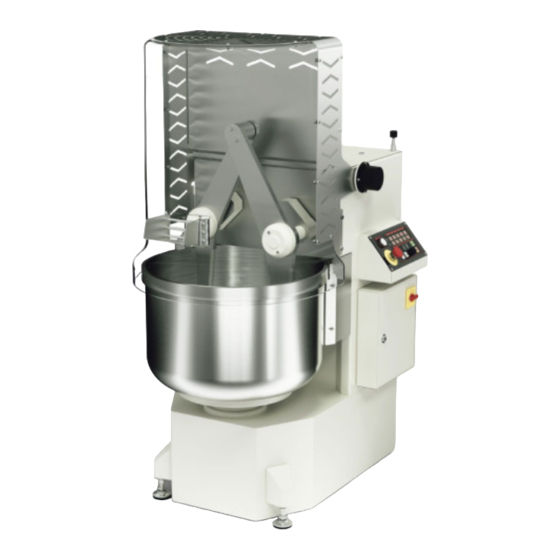
- Page 1 Plunging arms mixer ITWIN 55...
-
Page 3: Ce Declaration Of Conformity
CE DECLARATION OF CONFORMITY With the present the manufacturer DECLARES that the machine: Serial n°... To which this declaration refers to is in compliance with the relevant provisions of: - Directive 2006/42/EC of the European Parliament and of the Council of May 17, 2006 - Italian Legislative Decree of January 27, 2010 No. -
Page 4: M A Chine Composition
1. INTRODUCTION The machine has been designed for use in bakeries, pastry shops, pizzerias and in th food industry. CDesigned to get the best in terms of soft dough, where yeasts, both natural (mother yeast) an traditional, can work in the most suitable environment possible to develop their potential. Another strong point of this machine are the traditional Italian mixtures such as panettone Pandoro, colomba and focaccia. - Page 5 1.1 P R E A M B L E This user instruction manual is intended to be consulted by anyone employed in any capacity, who is in charge, and authorised to use and/or operate the plunging arms mixer. It is also intended for employers, managers and supervisors of the user company, who must read it carefully and understand it, so they can use it as a valuable support for the fulfilment of their obligations as required by the current laws and regulations on safety and health in the workplace.
- Page 6 Instructions for decommissioning or dismantling. This part is covered in Chapter 6. Before performing any operation relating to the machine carefully read the general instruction and specifications contained in this manual and obtain a good understanding of their purpose and meanings in order to acquire the necessary knowledge for the proper functioning of th machine, for proper maintenance of its parts, for an adequate knowledge of the safety devices as well as the residual risks that it presents, and therefore, for a correct use in safe conditions.
-
Page 7: Warranty Certificate
1.2 WARRANTY: VALIDITY AND CONDITIONS The MANUFACTURER guarantees the correct functioning and quality of this machine. There is a warranty period of 12 months from the date of delivery of the machine only if the warranty certificate indicated below is duly submitted within 15 days of receipt of the machine. The warranty is bound by a proper use of the machine and its maintenance according to the user instruction manual. - Page 8 1.3 INSTRUCTIONS AND GENERAL WARNINGS The MANUFACTURER disclaims all liability for damage to people, animals, property caused by failure to comply with the recommendations for the installation, use and maintenance as contained in this manual, and in particular the following: •Do not tamper with the safety devices with which the machine is equipped;...
- Page 9 1.3 INSTRUCTIONS AND GENERAL WARNINGS •The clothes worn by the operator must be tight-fitting and free of flapping parts (avoid jackets, open shirts, etc.); any long hair should be tied up (e.g. in a cap); work clothing should be appropriate to the sanitary requirements of the treated/processed food. •Do not allow entry to the room where the machine is used, or for anyone to approach the same, especially laymen, minors and anyone not expressly authorised;...
- Page 10 1.4PRINCIPALCIRCUMSTANCESINWHICHTHEMANUFACTURERDECLINESLIABILITY The manufacturer declines all responsibility for damage to people, animals, property, as well as for loss of production, resulting from: •Using the machine in any way or for products other than those expressly stated in this manual. •Commissioning and/or using the machine in combination with other machines (e.g. flour and/or water dosing machines), without having first checked and formally declared that the resulting assembly conforms with the provisions of the laws, directives, regulations, etc., which are in any way relevant to it.
- Page 11 1.5 TERMINOLOGY To increase the understanding of this manual, below are the terms used in it: • OPERATOR: person in charge /authorised /to use a machine. •MIXER MACHINE:This machine is suitable for dough used in pastry shops, bakeries, pizzerias. Its operating system which recreates the typical human movement of arms and hands, is at its most efficient for working leavened dough.
-
Page 12: Features Of The M Achine
2 FEATURES OF THE M ACHINE 2.1 Description and Intended Use The machine described in this manual is intended for the production of masses o homogeneous and workable (malleable) dough by mixing various ingredients (the mai ones are water, flour, salt and yeast) from which confectionery and bakery products ar derived with subsequent processing. -
Page 13: Description And Intended U S E
2.1 DESCRIPTION AND INTENDED U S E Stainless steel mixing bowl Performs a rotational movement.. Safety protection Made in thermoformed transparent PETG, protects the operator from the motion of the utensil and prevents the dough and flour from escaping. Control panel Allows you to program in manual, semi-automatic or automatic mode the number of turns and the start time. - Page 14 2.1 DESCRIPTION AND INTENDED USE The plunging arms mixer is essentially made up of: •A load-bearing structure, which consists of a base in welded painted steel (WITHOU LEAD AND SOLVENTS, ACCORDINGTO CURRENT FOOD REGULATIONS) (11). At the bas of the load-bearing structure there are stabilising feet (10). •The mixture bowl (1) is the container where the product to be mixed is put, kneading is ca ried out by the motion of the plunging arm which is made of stainless steel.
- Page 15 2.2 ELECTRICAL COMMAND AND CONTROL DEVICES M A N MODEL 1 Main ON/OFF electric switch to turn on the machine, thus allowing it to receive power from the mains Mushroom-shaped ‘‘EMERGENZA (EMERGENCY)’’ stop button which when pressed cuts power to all moving parts.To restore the motion of the machine you must release the emergency button (rotating it clockwise) It is recommended to use the emergency button only when there are emergency situations and not as a button to stop the machine.
- Page 16 2.2 ELECTRICAL COMMAND AND CONTROL DEVICES PRO MODEL 5 4 7 Main ON/OFF electric switch to turn on the machine, thus allowing it to receive power from the mains Mushroom-shaped ‘‘EMERGENZA (EMERGENCY)’’ stop button which when pressed cuts power to all moving parts.To restore the motion of the machine you must release the emergency button (rotating it clockwise) It is recommended to use the emergency button only when there are emergency situations and not as a button to stop the machine.
- Page 17 2.2 ELECTRICAL COMMAND AND CONTROL DEVICES INV MODEL 1 Main ON/OFF electric switch to turn on the machine, thus allowing it to receive power from the mains Mushroom-shaped ‘‘EMERGENZA (EMERGENCY)’’ stop button which when pressed cuts power to all moving parts.To restore the motion of the machine you must release the emergency button (rotating it clockwise) It is recommended to use the emergency button only when there are emergency situations and not as a button to stop the machine.
- Page 18 2.2 ELECTRICAL COMMAND AND CONTROL DEVICES INV/PROG MODEL Main ON/OFF electric switch to turn on the machine, thus allowing it to receive power from the mains Mushroom-shaped ‘‘EMERGENZA (EMERGENCY)’’ stop button which when pressed cuts power to all moving parts.To restore the motion of the machine you must release the emergency button (rotating it clockwise) It is recommended to use the emergency button only when there are emergency situations and not as a button to stop the machine.
- Page 19 2.2 ELECTRICAL COMMAND AND CONTROL DEVICES TOUCH MODEL 1 Main ON/OFF electric switch to turn on the machine, thus allowing it to receive power from the mains Mushroom-shaped ‘‘EMERGENZA (EMERGENCY)’’ stop button which when pressed cuts power to all moving parts.To restore the motion of the machine you must release the emergency button (rotating it clockwise) It is recommended to use the emergency button only when there are emergency situations and not as a button to stop the machine.
-
Page 20: Main Technical Features
2.3 MAIN TECHNICAL FEATURES MODELLO MODEL Dough capacity (min/max)* 5/48 5/56 5/64 Flour capacity (min/max)* 3/30 3/35 3/40 Water capacity (min/max)* 2/18 2/21 2/24 Bowl volume Water / flour min 1st/2nd speed 40/60 40/60 40/60 MAN - PRO Twin arms nverter from 25 to 75 from 25 to 75... -
Page 21: General Dimensions
2.4 GENERAL DIMENSIONS 61,5 61,5 61,5 691,5 Ø 802 66,5 1248 868,5 plunging arms mixer... - Page 22 Ø 802 66,5 1248 868,5 Ø 802 66,5 1248 868,5 2.5 PLATE OF THE M ACHINE MADE The figure below shows the identification ITALY plate of the machine. The plate of the machine is in screen- MODELLO printed aluminium and the data is indelible MODEL : to ensure it remains over time.
- Page 23 3. HANDLING, INSTALLATION, PREPARATION, USINGTHE MACHINE 3.1 Handling and transport of the machine The machine is supplied on a pallet, and is fixed to it, by means of a metal bar. The machine is protected by a protective nylon film, and also by a wooden crate, then covered in cardboard, fixed by means of plastic strapping to the pallet.
- Page 24 3. HANDLING, INSTALLATION, PREPARATION, USINGTHE MACHINE IMPORTANT: Do not directly expose the machine to sunlight or to heat sources (ovens, stoves, etc.), t prevent deterioration of plastic and electrical control components. IMPORTANT: If in the future should it be appropriate to move the machine to a place other than that of installation, carefully follow the criteria described above.
- Page 25 3. HANDLING, INSTALLATION, PREPARATION, USINGTHE MACHINE 1) The place of installation of the machine must have the following characteristics: •Opening which will allow the largest parts of the machine to pass. •Constructional features comply with current regulations. •An electrical system complies with current regulations, particularly with respect to the earthing system, the main board with related protection devices for protection against current overloads and short circuits.
- Page 26 3. HANDLING, INSTALLATION, PREPARATION, USINGTHE MACHINE 3.2 Checking the levelling of the machine The levelling of the machine is important. Make sure that the machine rests correctly on th floor and above all that there are no vibrations. The work station should be as flat as possible for th proper functioning of the machine itself.
- Page 27 3. HANDLING, INSTALLATION, PREPARATION, USINGTHE MACHINE ) Once the lifting kit is inserted the plunging arm mixer can be lifted. Simply lift it using the E marked hooks which are to be hooked to the lifting brackets. We reiterate to use a sturdy trap;...
- Page 28 3. HANDLING, INSTALLATION, PREPARATION, USINGTHE MACHINE Installation of the mixer - Select a suitable place to locate the machine respecting the minimum distances from th walls. These spaces are required for cleaning and routine maintenance operations, which als allow you to operate in conditions of safety avoiding possible dragging and/or crushing. •...
-
Page 29: Connection To The Electrical Mains
3. HANDLING, INSTALLATION, PREPARATION, USINGTHE MACHINE .3 Connection to the electrical mains The machine is supplied with an electrical power cord with a CEE plug three-phase + earth see Figure 17) Before supplying power to the machine, make sure that the line voltage is equal to that tated by the manufacturer and indicated on the identification plate. -
Page 30: Voltage Table
3. HANDLING, INSTALLATION, PREPARATION, USINGTHE MACHINE Standard for the safety of electrical plants For Italy electrical installations must satisfy, as well as the technical specifications of the CEI also relative decrees enacted by the Ministry of Economic Development 22/01/2008 no. 3 in implementation of article 11m, paragraph 13, letter a) of Law 248 of December 2, 2005) In particular, it requires that the installation is carried out by a professional with the necessar technical requirements, and registered with the appropriate register. - Page 31 3. HANDLING, INSTALLATION, PREPARATION, USINGTHE MACHINE 3.4 Electric connection - wiring diagram • Check that the mains voltage is equal to the voltage indicated on the CE plate of the machine. • The installation must be protected by a circuit breaker. •...
-
Page 32: Preparation Of The Machine
3. HANDLING, INSTALLATION, PREPARATION, USINGTHE MACHINE 3.5 Preparation of the machine The machine can and should operate only one person at a time; The turning on of the control panel will be at the side (See Figure 20) while the position that i normally occupies will be to the front (See Figure 21). -
Page 33: Using The Machine
3. HANDLING, INSTALLATION, PREPARATION, USINGTHE MACHINE 3.6 Using the machine Before starting normal work remember the following important points: 1) Before using the machine you must put the ingredients inside the bowl. N.B. Limit the dispersion of the ingredients in the environment and in the other components of the machine for reasons of hygiene and safety (for example the flour dust). - Page 34 3. HANDLING, INSTALLATION, PREPARATION, USINGTHE MACHINE 3.7 Production cycle of a dough motion of the machine The motor operates at a variable speed controlled via the control panel, the pulley, belt and mule pulley, which transmit the motion to the coupling shaft. The arms and the utensils follow the motion as indicated by the arrows (Figure 27) Simultaneously with the motion of the plunging arms...
-
Page 35: Emergency Button
3. HANDLING, INST ALLA TION, PREP ARA TION, USINGTHE MACHINE 3.8 Procedure for stopping the machine and subsequent restart In the event of a sudden stop check if there is power. Then check the safety devices, however the user’s safety is ensured by: •... - Page 36 3. HANDLING, INSTALLATION,PREPARATION, USINGTHE MACHINE 3.9 Education and training of personnel on machine use As repeatedly stated in this manual, the employer must provide workers with adequat information and education, including practical (training), on the correct and safe use of th machine (it must be simple and understandable with respect to the acumen that can b reasonably expected from the concerned parties).
-
Page 37: Maintenance
4. MAINTENANCE 4.1 Preamble Interventions can relate to routine maintenance or extraordinary maintenance. All maintenance, periodic or not, dealt with here can be understood as routine maintenance, unless otherwise specified; other interventions, not mentioned here, are to be considered as extraordinary maintenance;... - Page 38 4. MAINTENANCE 4.2 Maintenance and checks to be performed daily - Before starting any operation, implement the safety measures described in (chapter 4.1.). -At the end of the day/shift, or, if the product requires it, at the end of production, clean and disinfect the machine, paying particular attention to the parts that may come into contact, even accidentally, with food (for details see chapter 4.9).
-
Page 39: Replacement Of Components
4. MAINTENANCE 4.4 Replacement of components When and why should the safety micro-switch be replaced: A periodic monthly inspection of the proper functioning of the safety micro-switch, present inside the machine itself. The micro-switch is tested according to two basic parameters which are operation and positioning. - Page 40 4. MAINTENANCE When the mixer stops at the opening of the protection, this means that the micro-switch is working properly. IMPORTANT: The safety micro-switch must intervene when, in the case of the protection being lifted, a minimum opening is created between the upper edge of the bowl and the lower safety edge.
- Page 41 4. MAINTENANCE 4.5 Possible faults and/or anomalies We list below some possible faults and/or anomalies. The resulting action must be performed in accordance with the instructions, if existing, and in any case only after having implemented the safety measures described in par. 4.1. TABLE 4 POSSIBLE FAULTS AND/OR ANOMALIES Faults...
-
Page 42: Touch Panel
INV PANEL: Err = Emergency on /guard or safety carters open INV / PRO G PANEL: EE: Emergency on /guard or safety carters open TOUCH PANEL: triangle with exclamation point = Emergency on /guar or safety carters open 6. Spare parts In a separate file, which is an integral part of this manual, the assembly drawing of the machine is provided while the corresponding lists of components are provided at the end of the manual. - Page 43 4. MAINTENANCE 4.8 Cleaning and sanitizing the machine Before starting any operation, implement the safety measures described in chapter 4.1. In accordance with applicable laws, it is necessary to ensure the perfect hygienic conditions of the machine; it must be cleaned and disinfected thoroughly and as deep as possible, both externally and internally at the end of each day and/or work shift.
-
Page 44: Daily Cleaning
4. MAINTENANCE •ANNUAL : which includes all operations already listed with the addition of a general cleaning of the machine frame with a cloth and warm water. Measures for cleaning the machine: •Remove the residues of dough and/or flour that should rest on any part of the machine, especially in the cracks, gaps and corners. - Page 45 4. MAINTENANCE TABLE 5 CLEANING DIAGRAM Work phases Detergent Procedure Tools/equipment Note Roughlyclean, Start eliminateproduct manual, Spatula, scraper, straight after theend residues,ifnecessary, mechanical prop of production removesmall parts After thoroughly Foamer atlow Disassembleand washing withwater pressure clean the small (max. 60 °C) parts foamor manual;...
- Page 46 4. MAINTENANCE PERIODIC OPERATIONS: • Oil check: Check the oil level of the gear holder vat, the lowest pinion must draw oil to lubricate the other gears. To add oil only use: ’ LUBREN OIL 1500’’. •Tensioning of the belts: Regularly check that all the machine belts are taut, inspect their wear and if necessary provide for their replacement which must however be carried out at the slightest sign of attachment and/ or wear of the rubber of which they are made.
- Page 47 4. MAINTENANCE Phasing the connecting rods: When we replace the oil sealing rings and then loosen the locking screws, it is very important to reposition the connecting rods in their original position. ATTENTION: tightening in the wrong position causes serious mechanical damage to the bowl, the kneading arms and the gears !!! When repositioning the locking elements, before tightening the screws, we must put the...
- Page 48 5. SAFETY 5.1 Preamble The considerations, in the following chapter, are based on the assumption that: •The operator has read and understood the instructions and directions of this manual and, in particular, that the conditions and the intended use of the machine is known. •The machine is designed for a working environment for the processing of food products.
- Page 49 5. SAFETY • For non-observance of ergonomic principles •Injuries/damage to the body as a result of incorrect posture and/or movements and/or as a result of lifting and handling heavy loads (putting flour sacks into the bowl or containers with large quantities of water, removing masses of dough from the bowl, etc.) N.B.
- Page 50 5. SAFETY 5.2.3 How to check the safety devices Checks on safety devices must be carried out at the beginning of each day or shift. •Safety protection in PETG: A slight lifting even minimal of the protection causes the machine to stop immediately. In order to restart the machine simply lower the protection;...
- Page 51 5. SAFETY •Emergency stop button: With machine on (main switch to ON), press the emergency button: the button must remain pressed and mechanically held. By pressing the START button, no part of the machine should start. In order to control the START of the machine it is first necessary to return the switch to its normal up position, turn it clockwise to release it (Figure 40).
-
Page 52: Residual Risks
5. SAFETY Residual risks The residual risks that characterise the machine are the following and/or are related to the following stages: residual risk of gripping and dragging between bowl and base A residual risk of gripping and dragging remains if a person were to introduce a body part in the space between the bowl and the machine structure, the risk is greater, the greater the thrust with which the exposed person forces it (e.g. - Page 53 5. SAFETY Residual risk of flour dust This residual risk is almost irrelevant because the residual openings of the protection are so small that they do not permit flour dust to escape. Despite this it is still advisable to always start the machine at low speed and to keep it at that speed for at least the first 5 minutes, when there are ingredients in the bowl that are not mixed well, in order to limit as much as possible the emission of flour dust which at higher speeds would be much more relevant.
- Page 54 5. SAFETY 5.3 Risks of electrical origin The machine’s electrical equipment meets the main requirements of CEI EN 60204-1, depending on the type of machine and its intended use. It is reiterated that access to any electrical part, which is not a control device of normal use, and all operations of an electrical nature, even seemingly simple, should only be permitted to specialist technicians, with a high level of education, professionalism and experience and who possess the required knowledge to correctly and safely carry out the works.
- Page 55 5. SAFETY 5.4 Information on the noise emitted from the machine The machine running empty, rated as the worst case condition, emits an equivalent continuous sound pressure level A-weighted of less than 70 dB. The measurement was carried out with an instrument such as QUEST MOD. 1800 class I°. From this data we can infer that the machine does not produce annoying, harmful noise or requiring the use of headphones or earplugs.
-
Page 56: Safety Signs
5. SAFETY 5.5 Safety signs The following safety signs are applied to the machine: - 6 - RISK OF ELECTRIC SHOCK! (400VOLT) (Yellow background, black drawing and edges) plunging arms mixer... - Page 57 6. DISMANTLING Should you wish to proceed with the dismantling of the machine, you must separate its various components by material type and then arrange for their disposal in compliance with applicable laws and regulations. Contact companies who are specialised in the specific field of waste disposal who will undertake to perform the above in compliance with the applicable laws and regulations.
- Page 58 GENERAL DIMENSIONS / DIMENSIONI GENERALI 61,5 61,5 61,5 691,5 plunging arms mixer...
- Page 59 Ø 802 66,5 1248 868,5 Ø 802 66,5 1248 868,5 Ø 802 66,5 1248 868,5 plunging arms mixer...
- Page 60 SPARE PARTS ITWIN 45-55-65 A S S I E M E ALBERO D X - RIGHT SHAFT ASSEMBLY plunging arms mixer...
- Page 61 SPARE PARTS ITWIN 45-55-65 COD. A310101 DECRIZIONE DESCRIPTION ALBERO CORONA A310245-3 RIGHT / LEFT CROWN SHAFT DESTRO/SINISTRO A310246 CORONA DENTATA DESTRA RIGHTTOOTHED CROWN A310247 CONTRAPPESO INGRANAGGI GEAR COUNTERWEIGHT A310248 DISTANZIALE ALBERO SHAFT SPACER A310250 FLANGIA PORTA PARAOLIO FLANGE HOLDER OIL SEAL A310251 DISTANZIALE CUSCINETTO BEARING SPACER...
- Page 62 SPARE PARTS ITWIN 45-55-65 A S S I E M E ALBERO S X - LEFT SHAFT ASSEMBLY plunging arms mixer...
- Page 63 SPARE PARTS ITWIN 45-55-65 COD. A310102 DECRIZIONE DESCRIPTION ALBERO CORONA A310245-3 RIGHT / LEFT CROWN SHAFT DESTRO/SINISTRO A310247 CONTRAPPESO INGRANAGGI GEAR COUNTERWEIGHT A310248 DISTANZIALE ALBERO SHAFT SPACER A310250 FLANGIA PORTA PARAOLIO FLANGE HOLDER OIL SEAL A310251 DISTANZIALE CUSCINETTO BEARING SPACER COPERCHIO A310252 REAR CLOSING COVER...
-
Page 64: Spare Parts
SPARE PARTS ITWIN 45-55-65 A S S I E M E FULCRO BRACCIA - ASSEMBLY ARMS FULCRUMS plunging arms mixer... - Page 65 SPARE PARTS ITWIN 45-55-65 COD. A310103 DECRIZIONE DESCRIPTION A310254 CILINDRO FULCRO BRACCIA CYLINDER PIVOT ARMS A310255 ALBERO FULCRO BRACCIA SHAFT PIVOT ARMS A310273 RONDELLA CALETTATORE BIELLA WASHER, LOCKING ROD C00000163 VITE TSPCEI M 10 X 20 UNI 5933 SCREW TSPCEI M 10 X 20 UNI 5933 C00001008 SPINA ELASTICA UNI 6874 5 X 12 ELASTIC PIN UNI 6874 5 X 12...
- Page 66 SPARE PARTS ITWIN 45-55-65 A S S I E M E T R A S M I S S I O N E VA S C A - BOWL TRANSMISSION ASSEMBLY plunging arms mixer...
- Page 67 SPARE PARTS ITWIN 45-55-65 COD. A310104 DECRIZIONE DESCRIPTION A310258-3 ALBERO VASCA BOWL SHAFT A310259-3 FLANGIA CUSCINETTO VASCA BOWL BEARING FLANGE A310260-2 FLANGIA VASCA BOWL FLANGE A310263 GIUNTO RIGIDO RIGID JOINT ALBERO TRASMISSIONE A310264 REDUCERTRANSMISSION SHAFT RIDUTTORE A310316-1 DISTANZIALE CUSCINETTO VAS C A BOW L BEARING SPACER FLANGIA CENTRAGGIO A310317-2...
- Page 68 SPARE PARTS ITWIN 45-55-65 A S S I E M E PIGNONE CENTRALE - CENTRAL PINION ASSEMBLY plunging arms mixer...
- Page 69 SPARE PARTS ITWIN 45-55-65 COD. A310105 DECRIZIONE DESCRIPTION A310265 PIGNONE DI COMANDO CONTROL PINION COPERCHIO POSTERIORE A310266 SPROCKET REAR COVER DEL PIGNONE PULEGGIA DI COMANDO A310267 BOWL CONTROL PULLEY DELLA VAS C A A310268 PULEGGIA DI COMANDO CONTROL PULLEY A310269 COPERCHIO ANTERIORE PIGNONE SPROCKET FRONT COVER C00000536...
- Page 70 SPARE PARTS ITWIN 45-55-65 A S S I E M E BIELLA D X - RIGHT CONNECTING ROD ASSEMBLY plunging arms mixer...
- Page 71 SPARE PARTS ITWIN 45-55-65 COD. A310106 DECRIZIONE DESCRIPTION A310270 BIELLA CONNECTING ROD A310272 LAMIERA COPERTURE BIELLA SHEET COVER CONNECTING ROD A310273 RONDELLA WASHER C00000161 VITE TSPCEI M 10 X 30 UNI 5933 SCREW TSPCEI M 10 X 30 UNI 5933 C00004506 GRANO UNI 5923 10 X 16 GRAIN UNI 5923 10 X 16...
- Page 72 SPARE PARTS ITWIN 45-55-65 A S S I E M E BRACCIO D X - RIGHT ARM ASSEMBLY plunging arms mixer...
- Page 73 SPARE PARTS ITWIN 45-55-65 COD. A310107 DECRIZIONE DESCRIPTION A310275 COPERCHIO BRACCIA A R M COVER A310276 M O Z Z O BRACCIO D E S T R O RIGHT ARM HUB A310277 P E R N O BRACCIO D E S T R O RIGHT ARM PIN A S S I E M E BRACCIO E FORCA ASSEMBLY ARM AND FORK...
- Page 74 SPARE PARTS ITWIN 45-55-65 A S S I E M E BRACCIO S X - LEFT ARM ASSEMBLY plunging arms mixer...
- Page 75 SPARE PARTS ITWIN 45-55-65 COD. A310108 DECRIZIONE DESCRIPTION A310275 COPERCHIO BRACCIA A R M COVER A310279 MOZZO BRACCIO SINISTRO LEFT ARM HUB A310280 PERNO BRACCIO SINISTRO LEFT ARM PIN A 3 1 0 2 9 6 T 5 0 - T 6 0 - 1 ASSIEME BRACCIO E FORCA 55/65KG ASSEMBLY ARM AND FORK 55/65 KG A310296T40-1...
- Page 76 SPARE PARTS ITWIN 45-55-65 A S S I E M E RUOTA ANTERIORE - FRONT WHEEL ASSEMBLY plunging arms mixer...
- Page 77 SPARE PARTS ITWIN 45-55-65 COD. A3101 10 DECRIZIONE DESCRIPTION A310281 SUPPORTO RUOTA ANTERIORE FRONT WHEEL SUPPORT C00000172 VITE TSPCEI M 8 X 20 UNI 5933 SCREW TSPCEI M 8 X 20 UNI 5933 C00000859 VITE TE M 8 X 16 UNI 5739 SCREW TE M 8 X 16 UNI 5739 C00001245 RONDELLA UNI 6592 M8...
- Page 78 SPARE PARTS ITWIN 45-55-65 A S S I E M E TENDICINGHIA - BELT TENSIONER ASSEMBLY plunging arms mixer...
- Page 79 SPARE PARTS ITWIN 45-55-65 COD. A3101 1 1 DECRIZIONE DESCRIPTION A310210 TENDI CINGHIA BELT TENSIONER A310284 DISTANZIALE TENDI CINGHIA SPACER BELT TENSIONER C00001241 RONDELLA UNI 6592 M16 WASHER UNI 6592 M16 C00001243 RONDELLA UNI 6592 M12 WASHER UNI 6592 M12 C00005022 DADO UNI 5588 M 12 NUT UNI 5588 M 12...
- Page 80 SPARE PARTS ITWIN 45-55-65 A S S I E M E MONTAGGIO PROTEZIONI - ASSEMBLY OF PROTECTIONS plunging arms mixer...
- Page 81 SPARE PARTS ITWIN 45-55-65 COD. A3101 13 DECRIZIONE DESCRIPTION A310224-2 PROTEZIONE IN PETG BOWL PROTECTION IN PETG A310293T60-3 LAMIERA POSTERIORE 65KG REAR SHEET 65KG A310299T60-2 LAMIERA ELLA PROTEZIONE 65KG 65KG PROTECTION SHEET A310293T50-3 LAMIERA POSTERIORE 55KG REAR SHEET 55KG A310299T50-2 LAMIERA ELLA PROTEZIONE 55KG 55KG PROTECTION SHEET A310293T40-3...
- Page 82 SPARE PARTS ITWIN 45-55-65 A S S I E M E MOTORE VA S C A - BOWL MOTOR ASSEMBLY plunging arms mixer...
- Page 83 SPARE PARTS ITWIN 45-55-65 COD. A3101 14 DECRIZIONE DESCRIPTION A310227-1 LAMIERATIRAGGIO MOTORE SHEET FOR MOTORTENSIONING A310228 PERNO DELLA PIASTRA DEL MOTORE MOTOR PLATE PIN A310645 PULEGGIA DEL MOTORE 50 Hz MOTOR PULLEY 50 Hz C00000822 VITE TE M 10 X 60 UNI 5737 SCREW TE M 10 X 60 UNI 5737 C00000856 VITE TE M 8 X 30 UNI 5739...
- Page 84 SPARE PARTS ITWIN 45-55-65 A S S I E M E BIELLA S X - LEFT CONNECTING ROD ASSEMBLY plunging arms mixer...
- Page 85 SPARE PARTS ITWIN 45-55-65 COD. A310313 DECRIZIONE DESCRIPTION A310272 LAMIERA COPERTURE BIELLA ROD COVER SHEET A310273 RONDELLA CALETTATORE BIELLA WASHER, LOCKING ROD A310312 BIELLA CONNECTING ROD C00000161 VITE TSPCEI M 10 X 30 UNI 5933 SCREW TSPCEI M 10 X 30 UNI 5933 C00004506 GRANO UNI 5923 10 X 16 GRAIN UNI 5923 10 X 16...
- Page 86 SPARE PARTS ITWIN 45-55-65 A S S I E M E GENERALE M A C C H I N A - GENERAL MACHINE ASSEMBLY plunging arms mixer...
- Page 87 SPARE PARTS ITWIN 45-55-65 COD. A310600 N. Q DECRIZIONE DESCRIPTION A310101 ASSIEME ALBERO DESTRO RIGHT SHAFT ASSEMBLY A310102 ASSIEME ALBERO SINISTRO LEFT SHAFTASSEMBL Y A310103 ASSIEME FULCRO BRACCIA PIVOT ARMS ASSEMBLY A310104 ASSIEME ALBERO VASCA BOWL SHAFTASSEMBL Y A310105 ASSIEME PIGNONE CENTRALE CENTRAL PINION ASSEMBLY A310106 ASSIEME BIELLA DESTRA...
- Page 88 SPARE PARTS ITWIN 45-55-65 A S S I E M E MICRO PROTEZIONE - SAFETY SWITCH ASSEMBLY plunging arms mixer...
- Page 89 SPARE PARTS ITWIN 45-55-65 COD. A310635 DECRIZIONE DESCRIPTION A310633 BUSSOLA GUIDA ASTA ROD GUIDE BUSH A310634 ASTA PREMI INTERRUTTOREDI SICUREZZA SAFETY SWITCH ROD C00000536 VITE TCEI M 6 X 20 UNI 5931 SCREW TCEI M 6 X 20 UNI 5931 C00000545 VITE TCEI M 5 X 20 UNI 5931 SCREW TCEI M 5 X 20 UNI 5931...
- Page 90 SPARE PARTS ITWIN 45-55-65 ASSIEME PORTA QUADRO ELETTRICO - ELECTRICAL BOX DOOR ASSEMBLY plunging arms mixer...
- Page 91 SPARE PARTS ITWIN 45-55-65 COD. A310646 DECRIZIONE DESCRIPTION A310638 ASSIEME PORTA QUADRO ELETTRICO ELECTRICAL PANEL DOOR ASSEMBLY C00008677 CHIUSURA ELESA ELESA CLOSURE C00008676 CERNIERA ELESA ELESA HINGE C00007425 RONDELLA UNI6593 M5 WASHER UNI6593 M5 C00004495 GRANO UNI 5923 5 X 16 GRAIN UNI 5923 5 X 16 C00005026 DADO UNI 5588 M 5...
- Page 92 WIRING DIAGRAM PLUNGING ARMS MIXER INV-INV PROG plunging arms mixer...
- Page 93 WIRING DIAGRAM PLUNGING ARMS MIXER INV-INV PROG plunging arms mixer...
- Page 94 WIRING DIAGRAM PLUNGING ARMS MIXER INV-INV PROG plunging arms mixer...
- Page 95 WIRING DIAGRAM PLUNGING ARMS MIXER INV-INV PROG MORSETTIERA TERMINAL BLOCK plunging arms mixer...
- Page 96 WIRING DIAGRAM PLUNGING ARMS MIXER INV-INV PROG plunging arms mixer...
-
Page 97: Materials List
WIRING DIAGRAM PLUNGING ARMS MIXER INV-INV PROG 3-R4 WDR-120-24 ALIMENTATORE MEAN WELL WDR-120-24 DIN RA // POWER SUPPLY MEAN WELL WDR-120-24 DIN RA SYSTEL ELETTRONICA 3-S7 ZB4BV013 TESTA LAMPADA SPIA BIANCA LED // WHITE LED LAMP HEAD SCHNEIDER ELECTRIC ZBVB15 ELEMENTO A LED LUMINOSO BIANCO 24V // WHITE BRIGHT LED ELEMENT 24V SCHNEIDER ELECTRIC ZB4BZ009... - Page 98 WIRING DIAGRAM PLUNGING ARMS MIXER plunging arms mixer...
- Page 99 WIRING DIAGRAM PLUNGING ARMS MIXER plunging arms mixer...
Need help?
Do you have a question about the ITWIN 55 and is the answer not in the manual?
Questions and answers