Table of Contents
Advertisement
Quick Links
Advertisement
Table of Contents

Related Manuals for Permobil Trost Lite


Summary of Contents for Permobil Trost Lite
- Page 1 Tröst Lite Adjustable L ong-Term Care Bed Owner’s Manual...
- Page 2 Version 1.0 December 2023 © Permobil 2023 This document may not be reproduced, copied or used for purposes other than its intended use without the prior written consent of Permobil. This manual includes installation instructions as well as important safety and maintenance information for your Tröst Bed.
-
Page 3: Table Of Contents
Tröst Lite Adjustable Long-Term Care Bed Owner’s Manual Table of Contents Introduction Design and Functions ........................... 1 Specifications ..............................2 Safety Precautions............................3 Bed Assembly Overview ................................. 4 Inspection before unpacking ........................4 Damage during transport ........................5 Incorrect shipment ............................ 5 1 –... - Page 4 Tröst Lite Adjustable Long-Term Care Bed Owner’s Manual Optional Transport Trolley Assembly Assemble the transport trolley ......................... 44 Use the transport trolley ........................... 48 Bed Usage Inspect the bed before use ........................51 Move the bed into different positions....................52 Safe operation ............................
-
Page 5: Introduction
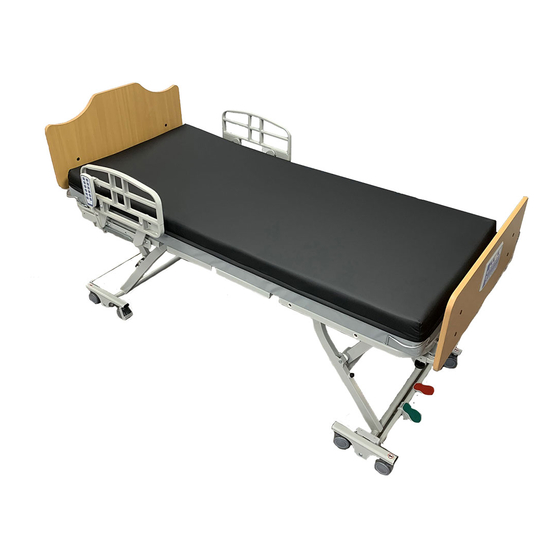
• length extender • half side rails • tall side rails • full side rails • assist bar • staff controller • battery backup • transport trolley The platform disassembles into 2 parts for easy assembly, transport and storage. www.permobil.ca... -
Page 6: Specifications
Weight capacity: Up to 500 lbs (226 kg). Platform position: low: 7.3" (18.5 cm); high: 28.3" (71.9 cm) Maximum Back Angle: 65 degrees ± 3 degrees Maximum Knee Angle: 30 degrees ± 3 degrees Electrical: 120V, 60 Hz Additional electrical specifications are indicated on the motor. www.permobil.ca... -
Page 7: Safety Precautions
The final selection and purchasing decision about the type of electric bed to be used is the responsibility of the user and his or her healthcare professional. Permobil is not responsible for inappropriate selections of models or features or improper mountings on the bed. -
Page 8: Bed Assembly
Your bed will arrive in 3-4 separate boxes, depending on the optional items included: • Platform, including electrical controller and hardware pack • Headboard and footboard • Optional side rails, assist bar, backup battery, staff controller, or length extender www.permobil.ca... -
Page 9: Damage During Transport
Contact your dealer or Permobil for further information. If there is any damage, it must be indicated on the bill of lading. Permobil must be informed of the situation within 24 hours of receipt of goods so that the carrier can be notified as soon as possible. -
Page 10: Unpack The Bed
3 - Remove corner protectors and outer wrap. Leave tie-wraps in place. Note that the bed is attached to a bracket on the packing skid. There is a box of hardware packed inside the foot platform. This box will be removed later in the assembly process. HARDWARE PACK www.permobil.ca... - Page 11 UNSCREW AND AND REMOVE REMOVE 5 - Pull and twist the black knobs securing the platform to the packing bracket to unpin the knobs. There are 2 knobs to unpin on each side of the platform. UNPIN 2 BLACK KNOBS www.permobil.ca...
- Page 12 After removing the bed assemblies, you will have a skid with 2 supports attached, and 4 loose bolts with wing nuts that are not needed to assemble the bed. It is recommended to store these packing materials so that you can securely store and transport the bed if necessary. www.permobil.ca...
-
Page 13: Assemble The Platform
The Tröst Lite Bed platform is provided in 2 pieces. You will arrange the head and foot platforms on the floor and then attach them in the middle. Two people are needed for platform assembly. STEPS 1 - Arrange the head and foot platforms on the floor as shown below. HEAD PLATFORM FOOT PLATFORM www.permobil.ca... - Page 14 2 - Lock the foot end wheels by sliding the locking clip down on each wheel. SLIDE THE CLIP DOWN TO LOCK EACH WHEEL 3 - Note the location of yellow and green connectors under the platform. NOTE THE LOCATION OF YELLOW AND GREEN ELECTRICAL CONNECTORS UNDER THE PLATFROM www.permobil.ca...
- Page 15 YELLOW WIRE 5 - Connect the green wire from under the head platform to the corresponding wire under the foot platform. Ensure that the arrows are aligned, and then close the cover. CONNECT GREEN CLOSE COVER ALIGN ARROWS WIRE www.permobil.ca...
- Page 16 7 - With the black knobs in the out position, two people need to lift the middle of the platforms so that you can place the locking inserts on each side of the foot platform into the corresponding slots on the head platform. www.permobil.ca...
- Page 17 8 - Ensure that each locking insert is in position in the slot as shown below. LOCKING INSERT SLOT ALIGN INSERTS ON FOOT PLATFORM INTO SLOTS ENSURE THAT THE LOCKING INSERT ON HEAD PLATFORM IS ALIGNED IN THE SLOT AS SHOWN √ × CORRECT INCORRECT www.permobil.ca...
- Page 18 Repeat on the other side of the bed. Ensure that the locking inserts are secured in place on each side. ENSURE THAT THE BLACK KNOB IS IN “OUT” POSITION THE “IN” POSITION 10 - Ensure that the platforms are secured together and the bed is flat. www.permobil.ca...
-
Page 19: Remove Cable Ties
2 - Lift the head deck so you can access the power cord and hand pendant. One person must hold the head deck in position. LIFT HEAD DECK 3 - Cut the cable tie on the power cord. 4 - Cut the cable tie(s) on the hand pendant. www.permobil.ca... - Page 20 5 - Move the hand pendant and power cord aside and then lower the head deck. 6 - Cut the 2 cable ties in the knee area of the foot deck. 7 - Cut the 2 cable ties on the end of the foot deck. www.permobil.ca...
- Page 21 2 – Assemble the platform 8 - Remove the cap from the power plug and then plug the bed in to an appropriate power outlet. A green light will illuminate on the controller system under the bed when the power is on. www.permobil.ca...
-
Page 22: Remove The Hardware Pack
STEPS 1 - Use the hand pendant to raise the bed enough so that you can remove the hardware pack. www.permobil.ca... -
Page 23: Test The Bed Positions
Raise head Lower knee Raise knee Lower back Raise back and knee and knee Lower entire bed Raise entire bed When finished, hang the hand pendant on the bed using the hook on the back of the hand pendant. www.permobil.ca... -
Page 24: Install Optional Side Rails
Tall rails and half side rails can be installed at the head or foot of the Tröst Lite Bed. Both tall and half side rails have the same installation instructions. Tool required: Allen key STEPS 1 - Open the side rail box and remove the side rails and hardware. TALL RAILS HALF RAILS www.permobil.ca... - Page 25 CENTER OF THE BED • If you are placing the rail on the head end you will use the head end holes indicated. • If you are placing the rail on the foot end you will use the foot end holes indicated. www.permobil.ca...
- Page 26 5 - Repeat for the other hole so you have two rods secured to the inside of the rail. 6 - Feed the rods on the side rail through both the outside and inside holes on the bed. FEED THE RODS THROUGH BOTH THE OUTSIDE AND INSIDE HOLES ON THE BED www.permobil.ca...
- Page 27 8 - Repeat for the half side rail on the other side of the bed, and for additional half side rails on the same side of the bed, if applicable. To move the slide rail, press the black unlocking clip. The rail snaps in place when it’s fully down. www.permobil.ca...
-
Page 28: Install Full Side Rails
1 - Open the full side rail box and remove the side rails and hardware. 2 - Remove the packaging from the side rails and hardware. Verify that you have 2 full rails, 4 washers, 4 screws, 4 spacers, 4 set screws, an Allen key and 4 rods. www.permobil.ca... - Page 29 The curved side of the foot end will face toward the bed. RAIL INSTALLATION OVERVIEW • ROD SLIDES IN TO BED • RAIL IS SECURED TO ROD • ROD IS SECURED AGAIN WITH SET SCREWS FOOT END ATTACHMENT HEAD END ATTACHMENT www.permobil.ca...
- Page 30 Press and hold the button on each rod as you feed it in so that the button engages in the middle hole. HEAD END ROD ATTACHMENT FOOT END ROD LOCATION ATTACHMENT LOCATION FIT ROD INTO ATTACHMENT PRESS AND LOCATION HOLD BUTTON ENGAGE THE BUTTON IN THE MIDDLE HOLE www.permobil.ca...
- Page 31 ONTO END OF ROD THE RAIL TO THE ROD 7 - Use a set screw to secure the foot end rod to a nut underneath the bed. Tighten using the Allen key provided. SCREW FASTEN THE FOOT END ROD UNDERNEATH THE BED www.permobil.ca...
- Page 32 THE BED SCREW 9 - Repeat for each end of each rail. 10 - To move the slide rail, pull the black knob under the head end to unpin it, and then slide the rail. UNPIN BLACK KNOB BLACK KNOB www.permobil.ca...
-
Page 33: Install Optional Assist Bar
STEPS 1 - Open the assist bar box and remove the rail and hardware. 2 - Remove the packaging from the assist bar and hardware. Verify that you have 1 assist bar, 2 rods, 4 pins, and 2 screws. www.permobil.ca... - Page 34 6 - Securely tighten the screw on the outside of the bar using a size 5 Allen key. ATTACH THE RODS TO THE INSIDE OF THE ASSIST BAR TIGHTEN SECURELY FEED THE RODS THROUGH BOTH THE OUTSIDE AND INSIDE HOLES ON THE BED www.permobil.ca...
- Page 35 END OF EACH ROD To move the assist bar, pull the knob out and then pull down on the black handle. 2 - PULL THE BLACK HANDLE TOWARD THE HEAD END OF THE BED 1 - PULL THE KNOB OUT www.permobil.ca...
-
Page 36: Install The Headboard And Footboard
1 - Open the head & footboard box and the hardware pack. 2 - Verify that you have a headboard (curved top), a footboard, 4 u-shaped supports, 4 mattress retainers (used later), and 4 screws. HEADBOARD FOOTBOARD 3 - Use the hand pendant to raise the bed. www.permobil.ca... - Page 37 Note that on the foot end you can leave extra space if you will be extending the bed platform length. PRESS THE BUTTON TO SLIDE A U-SHAPED BRACKET IN THE CHANNEL www.permobil.ca...
- Page 38 6 - Secure the headboard and footboard to the U-shaped brackets using the screws provided. Note that the brackets are on the outside of the headboard and on the inside of the footboard. BRACKETS ARE ON THE OUTSIDE OF THE HEADBOARD www.permobil.ca...
-
Page 39: Connect The Optional Staff Controller
2 - Lift the platform at the head end of the bed to access the controller. Use a screwdriver to press in and lift to detach each end of the cord protector on the bed controller. Remove the cord protector. REMOVE THE CORD PROTECTOR www.permobil.ca... - Page 40 Tröst Lite Adjustable Long-Term Care Bed Owner’s Manual 3 - Connect the staff controller to the purple connection port on the bed controller. 4 - Replace the cord protector on the bed controller. Press down so that it snaps into place. REPLACE THE CORD PROTECTOR www.permobil.ca...
- Page 41 6 - Test the staff controller functions. Raise Raise Raise Raise back entire bed head knee and knee Turn staff controller on Stop bed Unlock control from moving Flatten bed Lower entire bed for CPR Lower Lower Lower back head knee abd knee www.permobil.ca...
-
Page 42: Install The Battery Backup
3 - Lift the platform at the head end of the bed to access the controller. Use a screwdriver to press in and lift to detach each end of the cord protector on the bed controller. Remove the cord protector. REMOVE THE CORD PROTECTOR www.permobil.ca... - Page 43 6 - Locate the battery backup mounting plate in the center of the head end of the bed platform. 7 - Place the battery backup on the mounting plate. PLACE BATTERY BACKUP ON MOUNTING PLATE BATTERY BACKUP MOUNTING PLATE www.permobil.ca...
- Page 44 FASTEN THE BATTERY BACKUP TO THE MOUNTING PLATE TIGHTEN ALL 4 FASTENERS 10 - Let the batteries charge for 48 hours before testing. To test, unplug the bed. The controller should stay illuminated and function when the bed is unplugged. www.permobil.ca...
-
Page 45: Prepare The Bed For Use
(sold separately). STEPS 1 - Unpack the length extender. 2 - Insert the length extender into the holes marked 84" on the foot end of the bed platform. 3 - Ensure that the extender is secure, and opens flat. www.permobil.ca... -
Page 46: Install Mattress Retainers
If you installed the length extender you will not use the mattress retainers on the foot end of the bed. The mattress is sold separately from the Tröst Lite Bed. Place the bed in a flat position when installing the mattress. Be sure that any mattress used meets all applicable safety standards. www.permobil.ca... -
Page 47: Use The Bumper Bar
Simply flip each limiter over the wheel to ensure that the wheels don’t turn from side to side. Note that the wheels will still move forward and backward. FLIP THE DIRECTIONAL FLIP THE DIRECTIONAL LIMITER DOWN TO LIMITER UP TO ALLOW PREVENT WHEELS FROM WHEELS TO MOVE FREELY MOVING SIDE TO SIDE IN ANY DIRECTION www.permobil.ca... -
Page 48: Optional Transport Trolley Assembly
The Transport Trolley is sold separately and shipped in a separate box. The transport trolley is used to move the Tröst Lite Bed in a vertical or horizontal position. Assemble the transport trolley Tools required: Cable tie snipper, 19 mm wrench STEPS 1 - Unpack the Transport Trolley. www.permobil.ca... - Page 49 3 - Note that the pieces are color coded (2 pieces have blue dots, and 2 pieces have green dots). Start with the wheel assembly and support with the blue dots. START WITH THE 2 PIECES THAT HAVE BLUE DOTS www.permobil.ca...
- Page 50 REMOVE BLACK COVER CONNECT ASSEMBLY SUPPORT 5 - Ensure that the support moves freely in and out of the hook on the wheel assembly. ENSURE THAT THE SUPPORT SWINGS FREELY IN AND OUT OF THE HOOK www.permobil.ca...
- Page 51 Tröst Lite Adjustable Long-Term Care Bed Owner’s Manual Assemble the transport trolley 6 - Follow the same procedure to connect the 2 pieces with green color-coded dots. 7 - Secure each bracket to each wheel assembly with a washer and nut. Tighten securely. www.permobil.ca...
-
Page 52: Use The Transport Trolley
STEPS 1 - Remove the headboard and footboard by sliding the U-shaped brackets out of the channels on the bed support. PRESS THE BUTTON TO SLIDE THE U-SHAPED BRACKET OUT OF THE CHANNEL www.permobil.ca... - Page 53 3 - Slide the trolley support arms in completely until the raised part of the bracket is against the bed support. ENSURE THAT THE RAISED PARTS ON THE TROLLEY SUPPORTS ARE FLUSH AGAINST THE BED SUPPORTS 4 - Lower the bed so the wheels are off the floor. 5 - Unplug the bed power cord. www.permobil.ca...
- Page 54 6 - You can use the trolley to move the bed horizontally or you can rotate the trolley supports to move the bed vertically. Ensure that all wires are safely out of the way. ROTATE THE TROLLEY SUPPORTS TO MOVE THE BED VERTICALLY 7 - Use the trolley handle to move the bed. TROLLEY HANDLE www.permobil.ca...
-
Page 55: Bed Usage
Use the hand pendant to check all positions of the bed (see next section). When applicable for battery backup testing: After the bed has been plugged in for at least 48 continuous hours, unplug the power cord and test the battery backup by using the hand pendant. www.permobil.ca... -
Page 56: Move The Bed Into Different Positions
Always apply the brakes after moving the bed, and before a person sits or lies down on the bed. Check the bed to make sure the brakes have been applied. www.permobil.ca... -
Page 57: Using Side Rails
The bed can be used again only if it has been properly cleaned and examined. No electrical components should be changed by anyone other than a qualified technician. Before changing an electric component, unplug the power cable and the battery fuse. This must be done by a qualified technician. www.permobil.ca... -
Page 58: Maintenance
After the bed has been plugged in for at least 48 continuous hours, unplug the power cord and test the battery backup by using the hand pendant. All defects must be repaired immediately by a qualified and authorized technician. Only use Permobil replacement parts. www.permobil.ca... -
Page 59: Troubleshooting
• Move the bed all the way down and keep Motors Synchronization holding the down button for 3 seconds. are not issue functioning • Replace the motor. One of the Gear is stripped motors makes a grinding noise www.permobil.ca... - Page 60 Bed is not • Raise or lower the bed to its maximum or level when minimum height operating Uneven load raise and distribution lower functions www.permobil.ca...
-
Page 61: Warranty
The bed is warranted to be free from defects in material and workmanship under normal use and service for the warranty periods specified. Permobil reserves the right to substitute equal or superior quality materials during repairs and/or replacements. All repaired or replaced parts are guaranteed for whichever is greater: 1 year from the date of service or the life of the warranty.
Need help?
Do you have a question about the Trost Lite and is the answer not in the manual?
Questions and answers