Table of Contents
Advertisement
Quick Links
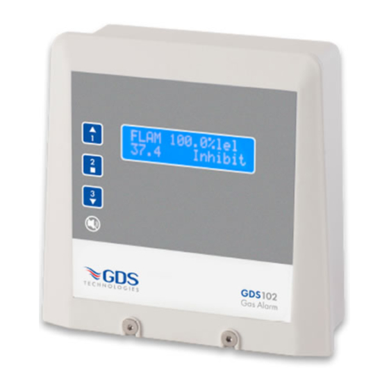
GDS 102
DUAL SENSOR GAS ALARM
A dual sensor unit supporting separate analogue
sensor operation is continuous with alternating displayed gas readings at five second
intervals. Function selection and adjustment is accessible via the front membrane panel
or laptop connection to
Installation
CONTROL UNIT: The control unit should be mounted in a position which is accessible and in the field of vision. Mains should be from a fused supply.
SENSORS: The positioning of sensors depends upon the type of gas to be monitored and its density with respect to air. See G973
Heavy Gases (Propane, Butane) – locate at 15 to 20 cm from floor level.
Lighter Gases (Methane, Natural Gas, Ammonia, Hydrogen) – locate at 5 to 10cm from the ceiling.
Carbon Monoxide Locate at 1.5 metres above floor level.
All equipment should be mounted away from direct heat and in accordance with its IP rating.
REFERENCE DOCUMENTS:
C1 144 Equipment Installation Guidelines
C1770 Wiring & Terminations for Sensors and Panels
G973 Gas Sensor Locations
C1548 Aspirated Sensor
On power up the unit will be inhibited for a 120 second warm up period displayed as a countdown on the display (this may be overidden by
pressing 1), a two sensor unit display readout will alternate at 5 second intervals, each reading may be held or released by pressing 1. To access the
main menu press 2 followed by the entry code 231, pressing 1 or 3 will allow travel through the menu and adjustment of settings, pressing 2 enables
access into the selected menu field and on completion pressing 2 will confirm your selection.
Main Menu
1
Exit
2
CH1 set up (sub menu) press 2 for access
3
CH2 set up (sub menu) press 2 for access
4
Delay to alarm. 0~255s
Default setting – 0 seconds
5
Latched/unlatched alarms (relay 1&2 cannot be reset when in alarm)
Default setting – latched
6
Exit
7
Normally energised/de-energised relays.
Default settings – de-energised
8
LED/relay test
9
Factory default settings – restore
10 Exit
11 Set 4 and 20mA output – calibrate
12 Relay 3 operating mode options – duplicate relay 1, 2, 4 or resettable
global alarm relay, channel 1/2 relay 1, 2, 3
13 Relay 4 operating mode options – fault or resettable global alarm relay,
channel 1/2 relay 1, 2, 3
14 Relay off delay. 0~255s
Default setting – 0 seconds
15 Exit
16 X input – external input to 0v, select text.
Default setting – flow fail
17 Select 4~20mA signal output to follow CH1/CH2 or highest reading.
Default setting – highest
18 Select open collector output – Inhibit indicator or resettable global switch.
Default setting – inhibit
19 User backup (settings)
20 Exit
20 Screen colour – Green/Blue
port.
J1 1 USB
and millivolt signal inputs,
4~20mA
Sub Menu
1
Exit
2
Enable/disable channel
3
Chanel inhibit – auto timeout – 60 minutes
4
Zerospan the channel
5
CANbus channel address set (Combi)
6
Gas range select
7
Exit
8
Gas type selection
9
Alarm level set (A₁, A₂, A₃)
10 Display gas reading, decimal point setting
11 Dead band setting – off, display only, full signal.
Default setting – off
12 CH2 input only (select mA fault trip level)
Default setting – 2.5 mA
The 102 may have been supplied without configured sensors (no
sensors enabled), in this case the following adjustments should be
carried out.
Channel 1 mV signal sensor (main menu 2)
Sensor supply may be measured between the two sensor voltage
test pins SV and TP10, adjust as required using the sensor supply
adjustment potentiometer SV, see sensor cell supply table.
The initial sensor zero adjustment is achieved by turning the zero
potentiometer RV4 until D9 zero LED just turns green. Test gas
should be applied to the sensor and a coarse adjustment made
using the gain calibration potentiometer RV3.
Channel 2 4~20mA signal sensor (main menu 3)
See sensor transmitters Tox/O
2
Ensure the sensor is in clean air, measure across test pins TP1/TP2
for a reading of 4mV = 4mA.
From this point on all further /future fine adjustments and settings
may be made through the menus.
Technical Sheet
ref C1943Av1
C1882 Flam C1883
377D2C
Advertisement
Table of Contents

Related Manuals for GDS 102


Summary of Contents for GDS 102
- Page 1 Default setting – 2.5 mA 12 Relay 3 operating mode options – duplicate relay 1, 2, 4 or resettable The 102 may have been supplied without configured sensors (no global alarm relay, channel 1/2 relay 1, 2, 3 sensors enabled), in this case the following adjustments should be 13 Relay 4 operating mode options –...
- Page 2 4~20mA Logging Intervals – Variable time, Rollover / stop MV Sensor GDS 102 Storage – 2,880 readings Access – laptop USB (J1 1) GDS website terminal download 3 wire CONTRAST Sensor Cell Supply Table 0V 4-20 CAT300A 2v/300mA SEM–2 4v/170mA CAT165 2.5v/175mA...
Need help?
Do you have a question about the 102 and is the answer not in the manual?
Questions and answers