
Related Manuals for GDS Combi


Summary of Contents for GDS Combi
- Page 1 C925 Manual No.194D1C Issue P.v2 TECHNOLOGIES LTD Combi OPERATING HANDBOOK www.gds-technologies.co.uk Tel. +44 (0)113 286 0166 Fax. +44 (0)113 287 8178 Email. sales@gds-technologies.co.uk...
-
Page 2: Table Of Contents
Action to be taken if the alarm activates ........................28 Appendix 1 (System Menu by number) ..........................29 Appendix 2 (Image of typical PC-Panel-PC text file) ......................35 Appendix 3 (Modbus Register Specification for COMBI 16 channel + CAN system) ............37 Appendix 4 (Event numbers) ............................37 Appendix 5 (Fuse Detials) ..............................38 Fig. -
Page 3: System Overview
This allows a system to be activated on an individual sensor basis as commissioning takes place. The gas types and alarm levels for Direct channels are set at the Combi panel but addressable types transmit this information to the panel. However, alarm levels for addressable sensors can be altered at the Combi panel or at the sensor itself. - Page 4 Use ENGINEER’S menu 16 to clear all addresses if required. Button action on the Combi panel can be protected by a Key lockout connection to prevent misuse. However, muting the buzzer which sounds if an event occurs can still be silenced by pressing the ACCEPT button (1).
-
Page 5: General Specification
Alarm settings 3 Alarm levels which are user selectable High, Low, and Over range Combi Panel Outputs RS232 data log, (up to 10 meter) CAN bus (up to 1Km) Modbus slave to an external Modbus Master (up to1Km @ 9600 baud) -
Page 6: Led And Lcd Indicators
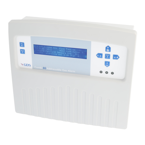
The type of gas and the text associated with this sensor is displayed. The third line displays the number of alarms and faults present in the Combi system. Normally these are zero. Additionally, the number of 4-20 and Addressable sensors in the system are displayed. - Page 7 The LEDs local to the panel are as follows: Alarm Internal/ Colour Description External Or Alarm on if any sensor currently has an over range alarm Lo Alarm on if any sensor currently has a low alarm Hi Alarm on if any sensor currently has a high alarm DC fail Amber on if battery is low...
-
Page 8: Buttons And Lockout
Buttons and Lockout 7 user buttons are provided on the front to allow control and setting up of the Combi system plus there is an internal PCB button. These buttons are also numbered and shown in brackets. e.g. button 3 is (3). -
Page 9: Entering A Password To Get To User Or Engineer Mode
Changing the engineers password is described later. The user password cannot be changed. Combi System Menu Index See Appendix 1 for further details. Note: User menu only contains items shown in red. Engineer's menu contains all items. View Modbus Reg... -
Page 10: Direct And Addressable Line Text
Direct and Addressable Line text The Combi system measures data on all active sensors. Direct sensors are done sequentially but addressable sensors send their data periodically when available (every few seconds). Each sensor has a text description (stored on the main pcb, not in the sensor) which describes physically where it is in the system and this text appears on the LCD as the most recent measurement is displayed. -
Page 11: Testing The Leds (7) And Relays (8)
The + (4) and – (2) buttons will change the displayed value. Pressing SELECT (3) will return to the ENGINEER’S menu. Note: that it is not possible to change the gas type for addressable sensors from the Combi panel. The gas type is set at the sensor itself and the Combi panel displays the information... -
Page 12: Gas Type Library
Gas Type Library Oxygen 0-25% two falling alarms Carbon Dioxide 1000ppm CO2b Carbon Dioxide 0-30%V CO2a Carbon Dioxide 0-2%V Hydrogen Sulphide 0-50ppm Carbon Monoxide 0-250ppm Sulpher Dioxide 0-10ppm Nitrous Oxide 0-100ppm Nitrogen Dioxide 0-10ppm Chlorine 0-10ppm Hydrogen 0-1000ppm Hydrogen Cyanide 0-25ppm Hydrogen Chloride 0-10ppm Ammonia 0-100ppm Ozone 0-2ppm... -
Page 13: Event To Remote Relay (23)
Event to remote relays (23) The following events can be assigned to remote 1-64 relays by using ENGINEER’S menu 23. 4-20 direct chan fail 4-20 direct chan hialarm 4-20 direct chan loalarm 4-20 direct chan oralarm chan fail chan hialarm chan loalarm chan... -
Page 14: Local And Remote Relays
In a MODBUS system that makes use of both these cable, both these LED’s flash periodically to indicate successful communication. Once the communication has started, the Combi system will monitor how long since the last command was received and if this is greater than 50 seconds a communications failure (COMMS FAIL) alarm will occur. -
Page 15: Set Up Network
This protocol is covered in a separate document known as MODBUS RTU protocol. In its simple form, the master will ask for the data kept in any of the 250 registers located in the Combi system and the Combi will reply with the requested register data. -
Page 16: Rs232 Data Log Output
RS232 data log output In addition to Modbus, an additional data stream showing actions within the COMBI system is available via the RS232 output. This consists of a 3 wire interface which can connect directly into the serial port (RS232) connection on a PC which is a 9 way D-type female connector (not supplied). -
Page 17: Data To And From A Pc Using Hyperterminal
PC is now waiting for data to be sent from the Combi system. (Note it is easier to save this file to the desktop initially). Using ENGINEER’S menu 30 (Data panel to PC) press select which should send data to the PC. -
Page 18: Real Time Clock
Line Description :T6, Port Hold 1 This line is the text for direct sensor 6 which will display on the LCD. For each direct input 20 characters can be assigned. *T4, AccomBlock This line is the text for addressable sensor 4 which will display on the LCD. -
Page 19: Changing Engineer's Password
4-20mA signal to input to the Combi (see sensor data sheets C893 & C894) This signal input to the Combi would produce a 0 to 100% of the signal range but a further level of calibration trimming is possible at the Combi panel. -
Page 20: Cell Replacement On Combi Sensors - Sensor Calibration
PCB. Fig 5 on page 43 and data sheets C893 & C894 at the end of this document detail the procedure for setting up a new sensor independent of the Combi panel and then when connected to Combi follow the above zero and span procedure. -
Page 21: Alarm Relay Off Timers
Alarm relay off timers The 8 relays on the PCB are allowed to take time to de-energise. For example, this delay could be used to keep fans running for a longer period after the gas alarm to allow a larger area to be vented. ENGINEER’S menu 24 allows each of the 8 relays to be selected by using the UP (1) and DOWN (5) buttons and then for each relay use the + (4) and –... -
Page 22: Defaulting Sections Of The Panel
Using the CAN network, 4 core (2 data + 2 supply) cable, a repeater can be connected which gives a user interface identical to the main Combi panel. In fact the data displayed on the repeater board is transmitted from the main panel. -
Page 23: Installation
Installation SITING THE SENSING HEADS A key feature of the installation is the correct positioning of the sensor. Several considerations must be taken into account, the most important being the density of the gas. Density (air = 1) Acetone Hydrogen-Sulphide 1.18 Acetylene 0.91... - Page 24 The control unit is designed for installation in a safe area only. Positioning of the instruments should be chosen with regard to the following points: • Away from sources of local heat with room for adequate ventilation • Within easy reach and audible distance of operating personnel •...
-
Page 25: Sensor Cable Routing
CAN channels. Spurs of four metres or less do not require an end of line link. The end of line link must be positioned on the very last sensor on each sensor cable run from the Combi. Direct Sensors:- Sixteen direct sensor inputs, each with three terminals, are available for terminating the two or three wire sensors (4-20mA devices) to the Combi. -
Page 26: Equipment Installation Guides
Equipment Installation Guidelines Standards Follow the correct electrical installation procedure and legislation (IEEE Regs) Junction Boxes DO check area classification for junction box suitability DO use boxes appropriate to the environment DO ensure correct IP rating for the environment DO use adequate sizes of field junction boxes DO allow for spare ways and future expansion DO mount field junction boxes at working height DO remember that water can’t get OUT of weatherproof boxes once it is inside! - Page 27 Terminations DO terminate cables to the correct points to prevent damage to the system DO sleeve and terminate earth wires correctly DO remain consistent in the allocation of wire colours DO remember to attach cable and termination markers to aid maintenance DO ensure that cable insulation extends right up to the throat of the terminal DO ensure that there are no bare wires or wire strands DO use the correct tool for crimp connections...
- Page 28 Testing DO complete the cable installation testing BEFORE final termination at either end DO record the cable loop resistance values to aid troubleshooting later Documentation DO record cable routing and equipment/junction box locations DO track all changes by updating the system documentation DO keep records adjacent to the equipment...
-
Page 29: Service - Routine Attention
Service – routine attention The owner or occupier of the premises should place the supervision of the system in the charge of a responsible executive, whose duty it should be to ensure the day to day operation of the system and to lay down the procedure for dealing with a gas alarm, (see below) or fault warning. -
Page 30: Appendix 1 (System Menu By Number)
Using UP (1) / DOWN (5) and SELECT (3) allows the date and time to be changed. Note, if the CAN communication connection is made to other Combi panels, the time from the lowest address panel will impose itself onto higher panels. So this means that the time should only be adjusted on the lowest address panel and then this new time will appear on other higher address panels. - Page 31 Addressable Zero and Span The first part of this menu allows you to zero an addressable CAN channel. The channel is selected by using UP (1) and DOWN (5) buttons and the reading itself is adjusted by pressing + (4) and – (2). This menu will timeout and the number of seconds left is displayed on the LCD.
- Page 32 Alter Gas Type and Range The gas type, default range, number of decimal places and deadband can be selected using this menu. Use UP (1) and DOWN (5) to choose the channel, and + (4) and – (2) to change the gas type.
- Page 33 Pressing SELECT (3) will exit this menu. Additionally, pattern 8765 321 can be redirected to 7 relays on the Combi input PCB. The fault relay 4 always remains as Fault but the remaining relays are assigned as follows: Low, High, Overange, Opt1, Opt2, Opt3, Opt4.
- Page 34 Seconds to Alarm When an alarm condition exists it is possible to delay the response and if the alarm still exists at the end of this delay then a normal alarm condition is recognised. This menu allows you to set this delay to a maximum of 255 seconds.
- Page 35 LTEL, STEL Alarms This menu allows you to set the time weighted average alarms for groups 5, 6, 7 and 8. Default Sections Sometimes it is required to default part of the data in the panel and this menu allows you to do this.
-
Page 36: Appendix 2 (Image Of Typical Pc-Panel-Pc Text File)
Appendix 2 Below is an example of a typical text file that can be sent to/from the COMBI system. PLEASE NOTE: 1) ‘ : ‘ = Direct Sensor, ‘ * ” = Addressable Sensor 2) Lines of the same command but different addresses have been deleted 3) The difference between patterns and groups is that there are 16 patterns, and 8 groups. - Page 37 Addres Chan 33 34 35 36 37 38 39 40 41 42 43 44 45 46 47 48 See above – but for addressable sensors 33-48 *Fault 0, 0, 0, 0, 0, 0, 0, 0, 0, 0, 0, 0, 0, 0, 0, 0, *first alrm 0, 0, 0, 0, 0, 0, 0, 0, 0, 0, 0, 0, 0, 0, 0, 0, *second alrm 0, 0, 0, 0, 0, 0, 0, 0, 0, 0, 0, 0, 0, 0, 0, 0, *third alrm 0, 0, 0, 0, 0, 0, 0, 0, 0, 0, 0, 0, 0, 0, 0, 0,...
-
Page 38: Appendix 3 (Modbus Register Specification For Combi 16 Channel + Can System)
Appendix 3 Modbus Register Specification for COMBI 16 channel +CAN system Function code 03 used througout to access these 16 bit unsigned registers Baud rate 4800,9600,19200 No parity 2 stop bits 2 channel known as Duty and standby (RS485) Register... -
Page 39: Appendix 5 (Fuse Detials)
The 9 Way D-type plugs into the PC COM port and the pre-wired sensor connector is inserted into J3 on the Combi Flam PCB (198 Issue P) and J3 on the Combi Tox PCB (204 Issue N). When Hyper-terminal on the PC set at 4800 baud (no handshake) and connected to the com port, the PC should now display the continuous sensor output . - Page 40 Worldwide internet access Description Part No Description Part No Combi Control Unit - 64 + 16 Sensors 160-100 20JF1 Flam / Toxic Gas Sensor SAFE AREA Combi Repeater Panel 160-200 40JF1 Flam / Toxic Gas Sensor SAFE AREA Combi 64 Way Data Logger Software...
-
Page 41: Fig. 3 (Combi Controller Network Configuration)
Fig. 3 Combi Controller Network Configuration CAN 2 CAN 2 Sensors Sensors CAN 1 CAN 1 Sensors CAN 1 Sensors CAN 1 Sensors CAN 1 Combi Network Controller Sensors Scans/controls up to x16 CAN 1 combi panels Sensors CAN 1... - Page 42 Fig. 4 Circuit Board details Power supply and Input / Outputs Front Panel PCB...
-
Page 43: Fig. 5 (System Wiring)
Fig. 5 System Wiring Mainboad to Sensor wiring Sensor Jumper configuration for TOX Board Addressable Sensor Control Unit 4~20 IN 4~20mA CAN 1 or 2 3-Wire Direct 4~20mA Signal Sensor Control Unit 4~20 IN 4~20mA 4~20mA Input 2-Wire Direct 4~20mA Signal Control Unit Sensor 4~20 IN... -
Page 44: Set Up Procedure For Flammable Sensors (C893)
The sensor bridge is zeroed by adjusting RV3 until the dual colour led D1 is off. (Or voltage V0 is 0.0v) Connect PC hyper terminal using RS232 Combi adaptor (part no. 160-510 and lead part no. 160-515) at 4800 baud connected to J3 and initialise the sensor using (C) calibration mode, then shift + ($) command from the keyboard. - Page 45 Using magnets (set up) The Combi sensors which have an LCD display fitted also incorporate 3 reed switches which can be activated using external magnets through the glass window of the flameproof XDIwin enclosure. These magnets do not act instantly and have to be in close proximity to L, M and R on the front display for a few seconds to activate a software setup function.
-
Page 46: Set Up Procedure For Toxic Sensors (C894)
Combi / XDI-XDIwin Toxic/Oxygen Sensor 4 / 3 / 2 wire sensor Data Sheet Set up procedure: 204D1C Issue N.v2 TECHNOLOGIES LTD ref C894 NEW SENSORS ARE SUPPLIED READY TO CONNECT TO A SYSTEM WITH ALL JUMPERS INSERTED. THIS PROCEDURE SHOWS HOW TO RECALIBRATE AS PART OF ROUTINE MAINTENANCE OR CELL REPLACEMENT. - Page 47 Using magnets (set up) The Combi sensors which have an LCD display fitted also incorporate 3 reed switches which can be activated using external magnets through the glass window of the flameproof XDIwin enclosure. These magnets do not act instantly and have to be in close proximity to L M and R on the front display for a few seconds to activate a software setup function.
-
Page 48: Auxillary Equipment Relay Switch Set-Up C1179
The CAN relay must also be set up to copy a group of 4 relays on one of two 32 way external relay boards. If a 32 way external relay unit is not being used the Combi system sees the 4 relays in the CAN relay as part of a virtual 32 way external board. -
Page 49: Channel 4~20Ma C1147
The eight channel 4~20mA output PCB allows signals in either sink or source mode to synchronised with the Combi 64 addressable and 16 direct sensors. By address selection on “S2”, the eight outputs can be selected for combinations of Combi sensors as detailed below. -
Page 50: 20Ma Input C1180
Press X to exit the calibration mode. 7. Connect to a combi panel and ensure that the sensor reports in correctly. Note: that if this sensor is at the end of the communication wires then it will need terminating by inserting jumper J1(EOL). The continuous data output when connected to HyperTerminal is the same format as for the Flammable sensor. -
Page 51: Combi Sensor - Location / Gas Type - Log
C1123 Main Controller Serial No. Relay programmed or used Sensor Direct Location Common CAN Relay 32 Way Group Type... - Page 52 GDS Technologies Ltd Fusion Point, Ash Lane Garforth, Leeds LS25 2GA Tel +44 (0)113 286 0166 Fax +44 (0)113 287 8178 sales@gds-technologies.co.uk ISO 9001 www.gds-technologies.co.uk TECHNOLOGIES LTD...
Need help?
Do you have a question about the Combi and is the answer not in the manual?
Questions and answers